Rolling bearing-rotor system damage vibration response quantitative calculation method

A vibration response and rolling bearing technology, which is applied in the direction of mechanical bearing testing, measuring devices, instruments, etc., can solve the problems of few coupling systems, inaccurate simulation results, and inability to quantitatively simulate the influence of the size of the damage area, and achieve the effect of accurate calculation results

Active Publication Date: 2014-04-09
XI AN JIAOTONG UNIV
View PDF2 Cites 18 Cited by
  • Summary
  • Abstract
  • Description
  • Claims
  • Application Information

AI Technical Summary

Problems solved by technology

One is to apply a series of continuous and equally spaced pulse forces to the bearing to simulate the situation that the rolling element passes through the damaged area each time. McFadden and Smith modeled the single-point damage of the bearing as a pulse force represented by an impact function (McFadden, P. D., Smith J. D.. Model for the Vibration Produced by a Single Point Defect in a Rolling Element Bearing[J]. Sound Vib.,1984, 96: 69–82.), and then based on this method, the multi-point defect on the inner ring of rolling bearing was studied Vibration response; the second idea is to establish a bearing or bearing-rotor dynamics model, and use a reasonable model to describe the rolling body passing through the damaged area according to the defect characteristics, and then obtain the bearing damage vibration response by solving the dynamic model, such as Kankar, Sharma et al established a 2-degree-of-freedom bearing dynamics model to study the nonlinear vibration response of damaged bearings (P.K. Kankar, Satish C.Sharma, S.P. Harsha. Vibration based performance prediction of ball bearings caused by localized defects[J]. Nonlinear Dyn, 2012, 69:847–875), most literatures use 2-degree-of-freedom or 3-degree-of-freedom bearing models to predict the damage vibration response of bearings, which has a certain gap with reality, and the simulation results are often not accurate enough, and cannot Quantitatively simulate the influence of the size of the damage area on the vibration response; in addition, most models study the bearing independently, and few studies regard the bearing and the rotor as a coupled system to study the generation and transmission of the vibration response of the entire system after the bearing damage occurs

Method used


Image

  • Rolling bearing-rotor system damage vibration response quantitative calculation method
  • Rolling bearing-rotor system damage vibration response quantitative calculation method
  • Rolling bearing-rotor system damage vibration response quantitative calculation method

Examples


Embodiment Construction

[0038] The present invention will be described in detail below in conjunction with the accompanying drawings.

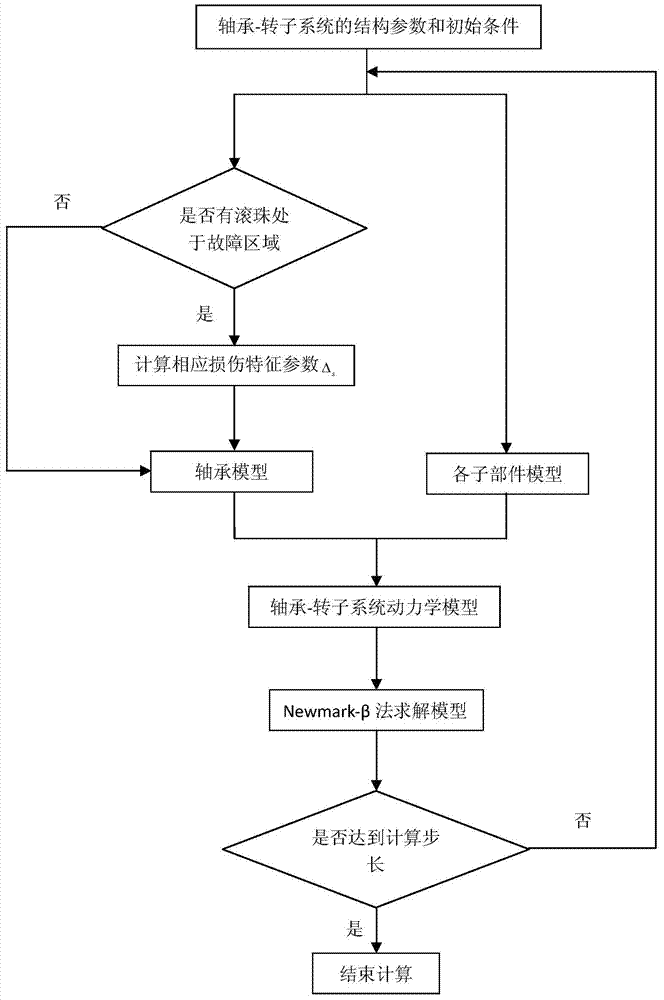
[0039] see figure 1 As shown, the present invention provides a method for quantitatively calculating the damage vibration response of a rolling bearing-rotor system, comprising the following steps:

[0040] 1) Obtain the structural parameters and initial parameters of the bearing-rotor system, the structural parameters include bearing parameters, geometric dimensions of sub-components, material property parameters and damage characteristic parameters; the initial parameters include the external force vector F of the bearing-rotor system, the rotor speed Ω;

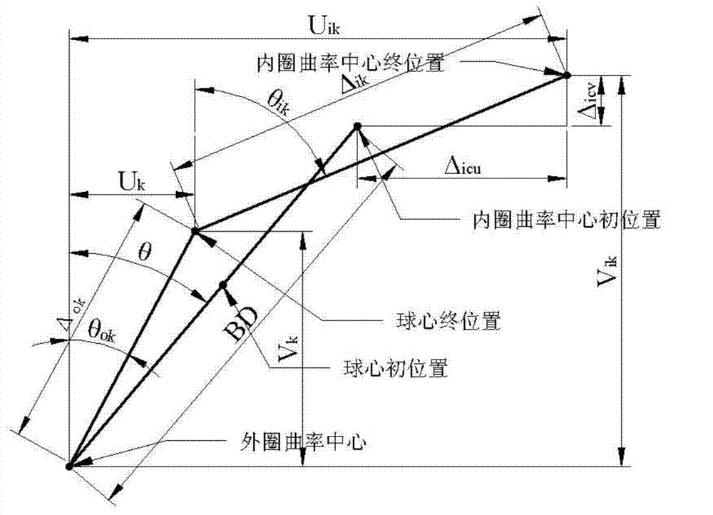
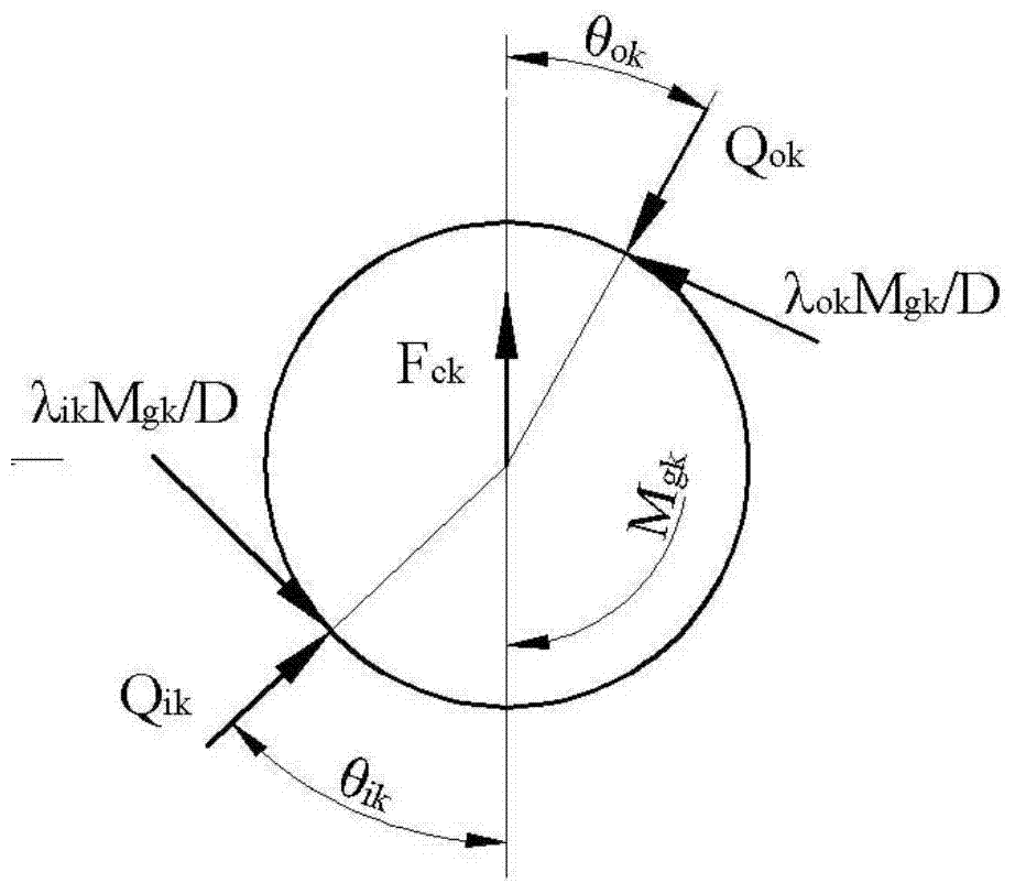
[0041] 2) Establish a five-degree-of-freedom bearing model based on the bearing parameters, and obtain the bearing stiffness matrix K of the bearing-rotor system B ;According to the geometric dimensions and material characteristic parameters of the sub-components, a finite element model is established to obtain...


PUM


Abstract

The invention discloses a rolling bearing-rotor system damage vibration response quantitative calculation method. The method comprises the steps that the structure parameter and the initial parameter of a bearing-rotor system are acquired; according to the bearing parameters, a five freedom degree bearing model is established, and a bearing stiffness matrix of the bearing-rotor system is acquired; according to the geometric size and the material characteristic parameter of a subcomponent, a finite element model is established, and a rotor stiffness matrix, a rotor gyroscopic matrix, and an equivalent mass matrix caused by a centrifugal force are acquired; a dynamics model of the bearing-rotor system is established; a time-domain integral method is used to solve the bearing-rotor dynamics model, so as to acquire the displacement vibration response of the bearing-rotor system. According to the invention, based on the finite element dynamics model, quantitative calculation can be carried out on vibration response generated by single point or multi-point damage of inner and outer rings of a bearing, and a basis is provided for the analysis and the diagnosis of a fault mechanism of the rotor-bearing system.

Description

technical field [0001] The invention relates to the field of bearing-rotor systems, in particular to a quantitative calculation method for damage vibration response of a rolling bearing-rotor system. Background technique: [0002] The rolling bearing-rotor system is a structural form widely used in rotating machinery equipment, and is the core component of the entire equipment. In the rolling bearing-rotor system, the rolling bearing is the weak link. According to statistics, in rotating machinery using rolling bearings, about 30% of mechanical failures are caused by damage to rolling bearings. After the bearing is damaged, there will be obvious vibration. Usually, the characteristics of the bearing fault can be extracted by collecting and analyzing the vibration signal. There are many studies in this area, and there are mature commercial solutions. However, there is relatively little research on the damage simulation of the rolling bearing-rotor system, resulting in a poo...

Claims


Application Information

Patent Timeline
Patent Type & Authority Applications(China)
IPC IPC(8): G01M13/00G01M13/04
Inventor 曹宏瑞李亚敏何正嘉牛蔺楷李文兴兰志俊
Owner XI AN JIAOTONG UNIV
Why Eureka
Try Eureka