Control method and control device of multi-section tomography detection of foundation piles
A tomography, multi-section technique, used in basic structure engineering, testing of basic structures, analysis of solids using acoustic/ultrasonic/infrasonic waves, etc.
- Summary
- Abstract
- Description
- Claims
- Application Information
AI Technical Summary
Problems solved by technology
Method used
Image
Examples
Embodiment 1
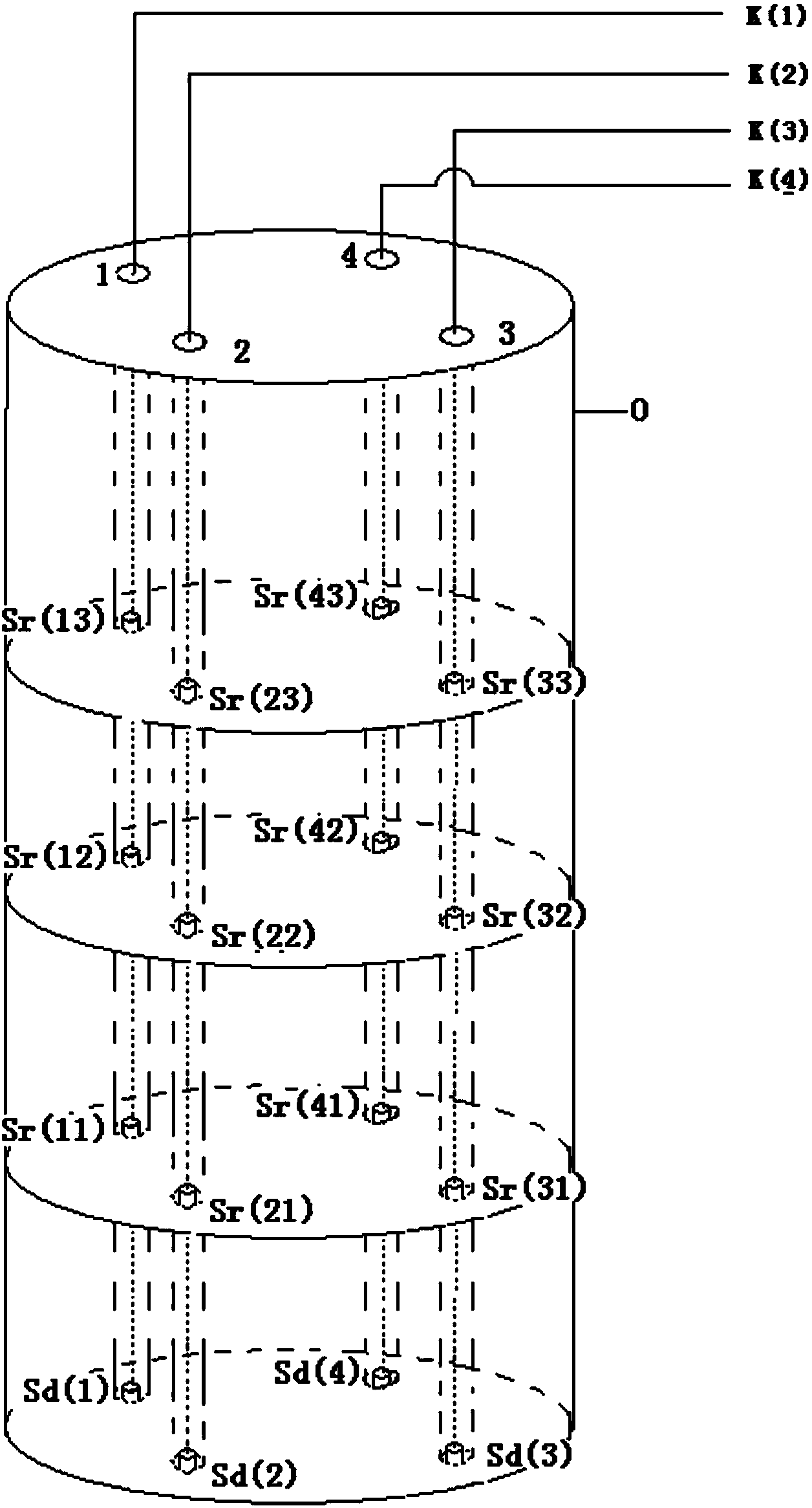
[0110] Pile inspection of four acoustic tubes. The length of the pile is 50m, and the acoustic tube numbers are 1, 2, 3, 4. There are 4 acoustic wave sensor groups S(1), S(2), S(3), and S(4), and the i-th acoustic wave sensor group consists of 3 Receiving sensors S(i1), S(i2), S(i3) and a receiving and transmitting duplex sensor Sd(i) are composed, and the distance between sensors is 0.10m.
[0111] A multi-section tomography (CT) detection and control method for foundation piles based on the acoustic wave transmission method, the steps of which are:
[0112] 01. Place the 4 acoustic wave sensor groups S(i) respectively at the bottom of the 4 acoustic tubes of the foundation pile, see image 3 . The 4 acoustic wave sensor groups S(i) are respectively connected with the 4 detection modules K(i) of the acoustic wave instrument I, and the cables of the 4 acoustic wave sensor groups S(i) can drive the height position encoder FMA to roll during the synchronous lifting process. ;...
Embodiment 2
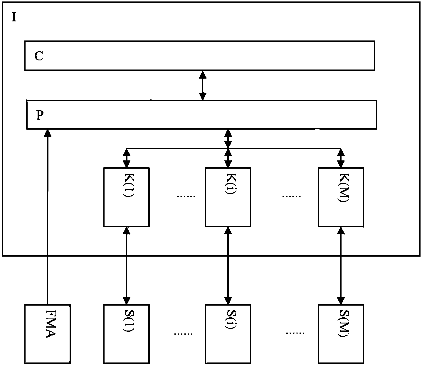
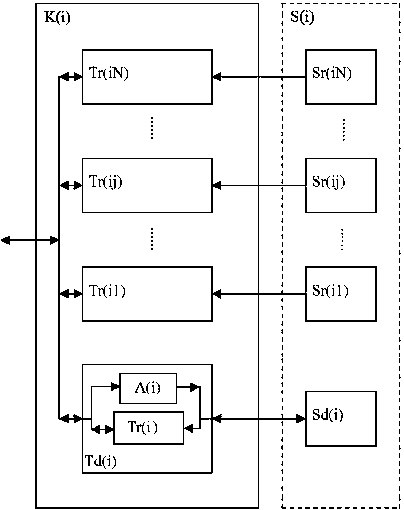
[0140] according to Figure 5 , Image 6 It can be seen that a multi-section tomography (CT) detection control device suitable for foundation pile detection with four acoustic tubes buried: it consists of an acoustic wave instrument I, a height position encoder FMA, and four acoustic wave sensor groups S (1 ), S(2), S(3), and S(4). Among them, the acoustic wave instrument I is composed of a computer system C, a control unit P, and 4 detection modules K (1), K (2), K (3), and K (4). Each detection module K (i) (i =1,...,4) are composed of 3 receiving channels Tr(ij) (j=1, 2, 3), 1 transmitting and receiving duplex channel Td(i), and the transmitting and receiving duplex channel Td(i) It consists of 1 receiving channel Tr(i), 1 acoustic wave transmitter A(i), and each acoustic wave sensor group S(i) (i=1, 2, 3, 4) consists of 3 acoustic wave receiving sensors Sr (ij ) (j=1, 2, 3), a sound wave transmitting and receiving duplex sensor Sd(i). Three acoustic wave receiving sens...
Embodiment 3
[0146] A half-duplex connection mode between a transmit-receive duplex channel Td(i) and a receive-transmit duplex sensor in the prior art. See Figure 7 . The transmitting and receiving duplex channel Td(i) has only one set of piezoelectric devices Crys1. When set to the transmitting state, the control module P controls R(i1) to be closed and R(i2) to be disconnected, and the corresponding acoustic wave transmitter A(i) is connected to the piezoelectric device Crys1 of the receiving and transmitting duplex sensor Sd(i), The corresponding receive channel Tr(i) is disconnected from the piezoelectric device Crys1 of the receive-transmit duplex sensor Sd(i). When set to the receiving state, the control module P controls R(i1) to be disconnected and R(i2) to be closed, and the corresponding acoustic wave transmitter A(i) is disconnected from the piezoelectric device Crys1 of the receiving and transmitting duplex sensor Sd(i) , the corresponding receiving channel Tr(i) is connec...
PUM
 Abstract
Description
Claims
Application Information
 - R&D
- Intellectual Property
- Life Sciences
- Materials
- Tech Scout
- Unparalleled Data Quality
- Higher Quality Content
- 60% Fewer Hallucinations
Browse by: Latest US Patents, China's latest patents, Technical Efficacy Thesaurus, Application Domain, Technology Topic, Popular Technical Reports.
© 2025 PatSnap. All rights reserved.Legal|Privacy policy|Modern Slavery Act Transparency Statement|Sitemap|About US| Contact US: help@patsnap.com


