High-speed railway supply arm shunt tripping protection method based on impedance characteristics

An impedance protection, high-speed railway technology, applied in emergency protection circuit devices, electrical components, etc., can solve the problems of high load current of high-speed EMUs, unable to meet the selectivity of protection, unable to identify high-resistance faults at the end, etc. Small, improve the protection sensitivity, the effect of large fixed value

Active Publication Date: 2014-04-09
SOUTHWEST JIAOTONG UNIV
View PDF3 Cites 16 Cited by
  • Summary
  • Abstract
  • Description
  • Claims
  • Application Information

AI Technical Summary

Problems solved by technology

[0004] Problem 1. The existing protection method only considers the measured impedance and current of the substation. When a fault occurs between the AT station and the partition station, it is impossible to judge whether the fault occurred on the uplink power supply arm or the downlink power supply arm. Therefore, when any location occurs When a fault occurs, the substation will jump off the two power supply arms, and the power failure range is large, which cannot meet the selectivity of protection
[0005] Problem 2. Due to the need to realize fault isolation through the cooperative action of reclosing of substations, AT stations and partition stations, it takes a long time to restore power supply, which cannot meet the quick action of protection
[0006] Problem 3. Due to the large load current of the high-speed EMU, the existing protection method should be set according to the maximum load current where the substation is avoided. The large setting value makes it impossible to identify the high-resistance fault at the end

Method used


Image

  • High-speed railway supply arm shunt tripping protection method based on impedance characteristics
  • High-speed railway supply arm shunt tripping protection method based on impedance characteristics
  • High-speed railway supply arm shunt tripping protection method based on impedance characteristics

Examples


Embodiment Construction

[0028] The present invention will be further described below in conjunction with the accompanying drawings and specific implementation. The drawings and specific embodiments do not limit the scope of protection claimed by the present invention.

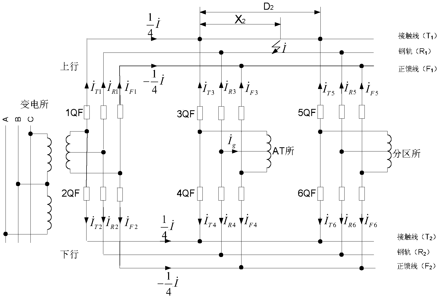
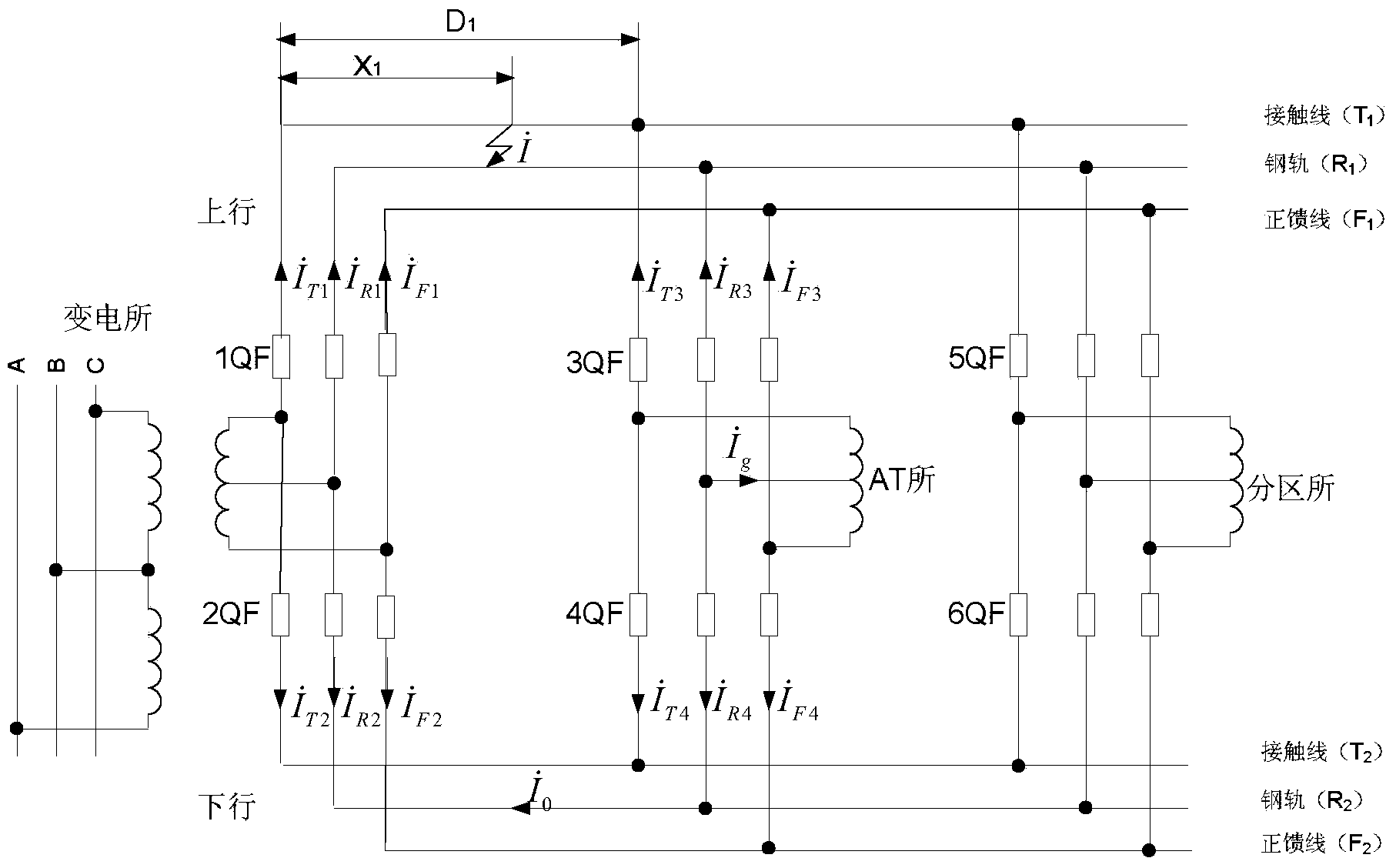
[0029] In an AT traction power supply system, the calculation formula for measuring impedance is generally:

[0030] Z i = U · s I · Ti - I · Fi (Formula 1)

[0031] in, is the ground voltage of the contact line busbar or the ground voltage of the positive feeder busbar, and s is the substation, AT station or divisional station respectively; are the contact line current and the positive fe...


PUM


Abstract

The invention discloses a high-speed railway supply arm shunt tripping protection method based on impedance characteristics. The method is realized through impedance protection elements distributed in a substation, an AT station and a subarea station in a scattered mode and through a communication network, wherein the quadrangular operation characteristics are adopted for the impedance protection elements. Each impedance protection element can transmit shunt tripping instructions to other impedance protection elements or receive the shunt tripping instructions from other impedance protection elements on the same supply arm through the communication network to rapidly isolate a fault supply arm. The impedance protection elements of the substation and the impedance protection elements of the AT station jointly protect all power supply sections between the substation and the AT station. The impedance protection elements of the AT station and the impedance protection elements of the subarea station jointly protect all power supply sections between the AT station and the subarea station. When a fault of any impedance protection element is detected, a breaker of the fault supply arm in the station is tripped off, a shunt tripping instruction is transmitted to the other impedance protection elements on the same supply arm, the other impedance protection elements receive the shunt tripping instruction and then trip off the corresponding breakers, and consequently the fault supply arm is rapidly isolated, and power supply of the other supply arm which is connected with the fault supply arm in parallel can not be influenced.

Description

technical field [0001] The invention belongs to the field of high-speed electrified railway traction power supply system, and the invention relates to the protection of electrified railway traction network adopting parallel autotransformer (AT) power supply mode. Background technique [0002] Since electrified railways adopt the method of sliding contact between the pantograph and the traction network, the failure rate of the traction network is much higher than that of the power line. Therefore, the relay protection of the traction network is very important, which is directly related to the power supply reliability of the high-speed railway. my country's high-speed railway generally uses fully parallel AT traction network to supply power to EMUs. The load and traction network structure are very different from those of the power system. Methods in the power system, such as fault component method, model identification method, comprehensive impedance method, traveling wave The...

Claims


Application Information

Patent Timeline
Patent Type & Authority Applications(China)
IPC IPC(8): H02H7/28
Inventor 韩正庆刘淑萍高仕斌
Owner SOUTHWEST JIAOTONG UNIV
Why Eureka
Try Eureka