Electric break motor

A technology of electric braking and electric motor, applied in the direction of electrical components, electric components, controlling mechanical energy, etc., can solve the problems of large-scale braking parts, limit of instant braking of motor shaft 2a, complex and cumbersome design structure, etc., and achieve simple design structure , the effect of saving power consumption

Active Publication Date: 2014-04-09
李德昌
View PDF4 Cites 7 Cited by
  • Summary
  • Abstract
  • Description
  • Claims
  • Application Information

AI Technical Summary

Problems solved by technology

[0004] But, the described liner 11 and the disc 9 of the motor brake 1 of the above-mentioned prior art are all flat plate-shaped forms, and the direction in which they contact each other to generate friction and the direction in which the motor shaft 2a rotates are because they are perpendicular to each other, and the friction that occurs The force cannot be completely transmitted to the direction of rotation of the motor shaft 2a, and slip occurs on the contact surface of the lining 11 and the disc 9, thereby limiting the immediate braking of the motor shaft 2a
[0005] In addition, in the above brake structure, in order to brake instantly, it is necessary to increase the pressing force that can increase the restoring force of the compression spring 7 and push the liner 10 to the disc 9. In this case, the drive During the motor 2, in order to separate the contact between the disk 9 and the lining 11, it is necessary to increase the magnetic field of the electromagnetic assembly part 4 that can make the compression spring 7 fully pressed, thus causing the compression spring 7, electromagnetic assembly part 4. Problems such as large-scale brake parts
[0006] Further, the motor brake 1 of the above-mentioned prior art has a structure in which a braking force is applied on the motor shaft 2a exposed outside the motor 2, and a module separate from the motor 2 is configured, resulting in an excessively large volume of the motor equipment as a whole, And its design structure is too complex and cumbersome

Method used


Image

  • Electric break motor
  • Electric break motor
  • Electric break motor

Examples


Embodiment Construction

[0031] The purpose, features and advantages of the above-mentioned present invention will be described in detail as follows. Hereinafter, preferred embodiments of the present invention will be described in detail with reference to the accompanying drawings of the present invention.

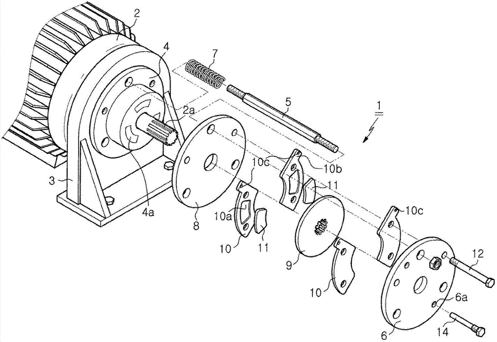
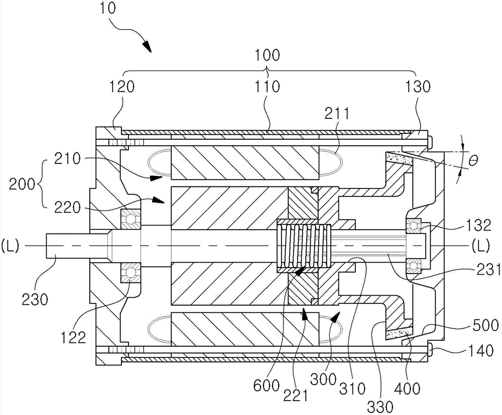
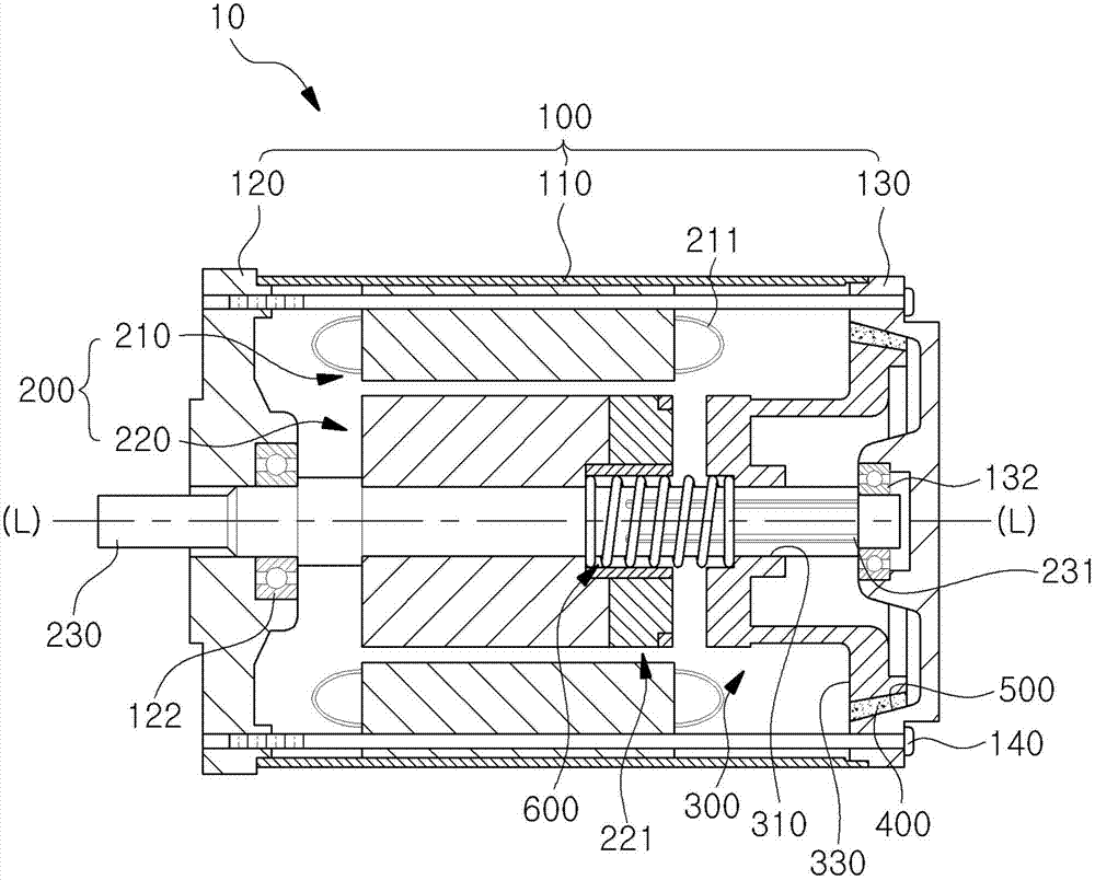
[0032] In the electric brake motor 10 of a preferred embodiment of the present invention, in order to make the motor shaft 230 stop rotating when the drive power supply is cut off, the direction in which the friction force occurs and the direction in which the motor shaft 230 rotates are opposite to each other, so that even if the magnetic field Relatively weak, it can also achieve instant braking. Such as Figure 2 to Figure 5 As shown, it includes: a cover part 100 , a rotary drive part 200 , a clutch part 300 , a friction lining 400 , a disk part 500 , a pressure spring 600 and a magnetic field deflection part 221 .

[0033] Here, the cover portion 100 is a cover structure formed outside the ...


PUM


Abstract

The invention discloses an electric break motor. The motor comprises a case, a front cover and a rear cover; a stator inside the case, and a rotation driving unit of a rotor, wherein the rotation driving unit is in the middle of the stator, rotates through power supplied by a driving power source and is formed by connection in the middle penetrating the motor; a cylindrical clutch unit sliding vertically along extension of a motor shaft, made from magnetic material, moving along a rotor direction and pulled by a magnetic field formed on the rotor when power is supplied by the power source; a friction liner that reduces gradually toward the rear in terms of external diameter and is arranged, in an inclined manner, on the circumference of the other outer side of the clutch unit; a disc unit that gradually reduces in internal diameter toward the rear, is disposed, in an inclined manner, on the inner circumference of the rear cover to be opposite to the friction liner, and contacts the friction liner along with sliding of the clutch unit to generate friction; and a pressing spring between the rotor and the clutch unit on the motor shaft and applies pressure to the clutch unit toward the rear cover in an elastic manner.

Description

technical field [0001] The present invention relates to an electric brake motor, and more particularly, to an electric brake motor capable of stopping rotation of a motor shaft when a driving power source installed inside the motor and capable of rotationally driving the motor is cut off. Background technique [0002] figure 1 It is a block diagram of a conventional electric motor brake. Such as figure 1 As shown, in the motor brake 1 of the prior art, when power is supplied to the motor 2, the electromagnet 4a of the electromagnetic assembly part 4 is also powered. 4a, the disk 9 and lining 11 lose friction, and the motor 2 is driven. [0003] On the contrary, in the process of driving the motor 2, in order to stop it, when the power is cut off, the electromagnet 4a loses its magnetic force, and the brake plate 8 leaves the electromagnet 4a due to the restoring force of the compression spring 7, and pushes the liner 10 to the On the disk 9 side, the lining 11 rubs again...

Claims


Application Information

Patent Timeline
Patent Type & Authority Applications(China)
IPC IPC(8): H02K7/102F16D55/24F16D121/20
CPCH02K7/106H02K7/112
Inventor 李德昌
Owner 李德昌
Why Eureka
Try Eureka