Roller shade with a brake

Inactive Publication Date: 2016-08-25
DOMICET
View PDF0 Cites 8 Cited by
  • Summary
  • Abstract
  • Description
  • Claims
  • Application Information

AI Technical Summary

Benefits of technology

The invention describes a brake mechanism for a shading device that works using magnetism. The brake is called an eddy current brake and it is preferred because it is quieter and quieter to use. It uses a magnetic field created by a permanent magnet or an electromagnet to provide the braking force. This brake does not wear out easily and is suitable for use in situations where speed and efficiency are important. The eddy current brake is particularly useful for unwinding continuous material. The brake is designed to have an air space between its components, so there is no abrasive contact or friction. This ensures the shading device is durable and resistant to damage. The magnetic circuit of the brake is closed, which means the material used for the brake's shaft does not need to be critical. The brake can be easily designed for different shoma tub sizes and is efficient in its use of magnets.

Problems solved by technology

In all these cases, the raising results in a hard collision and a loud sound and the shade can be damaged.

Method used


Image

  • Roller shade with a brake
  • Roller shade with a brake
  • Roller shade with a brake

Examples


first embodiment

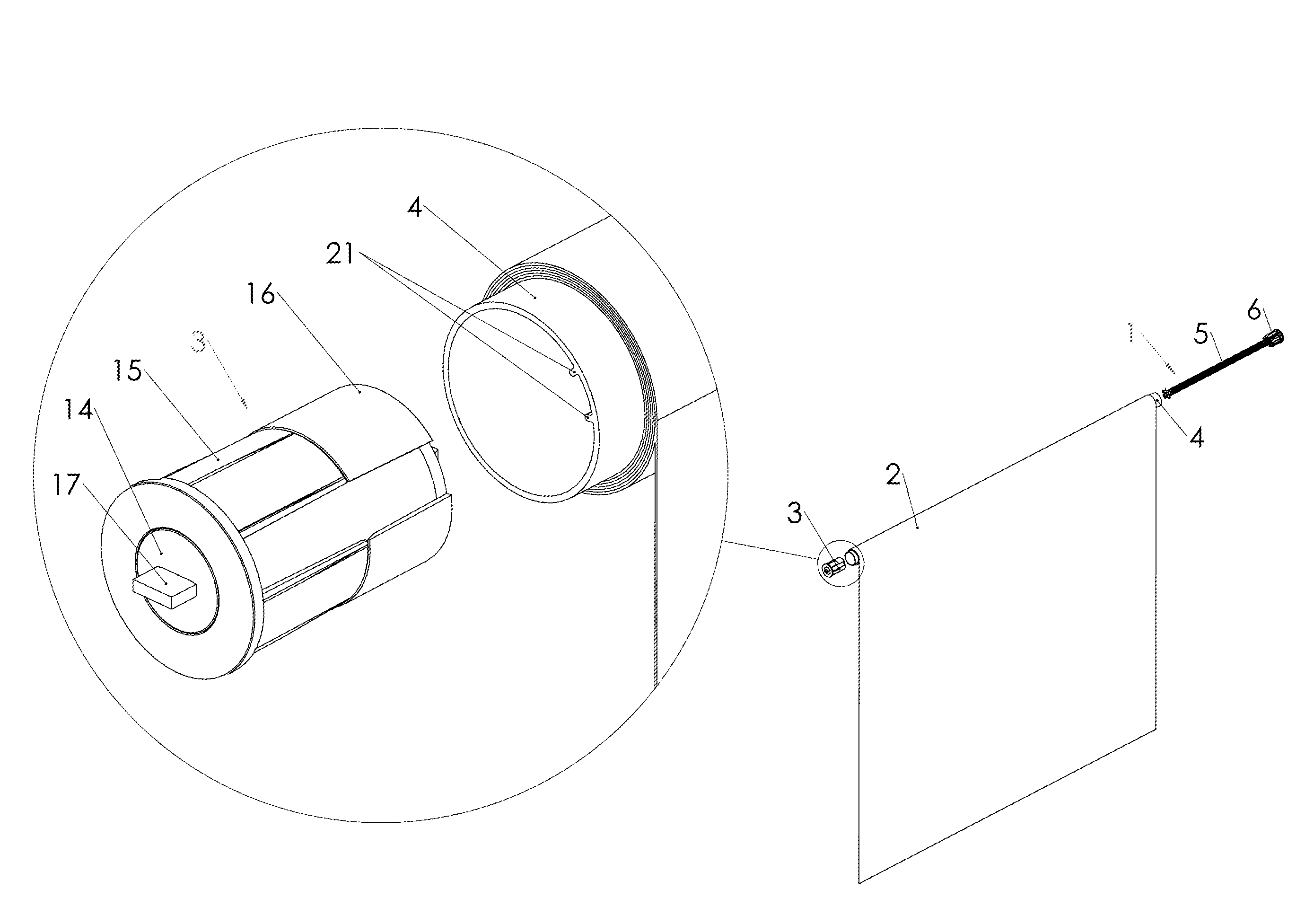
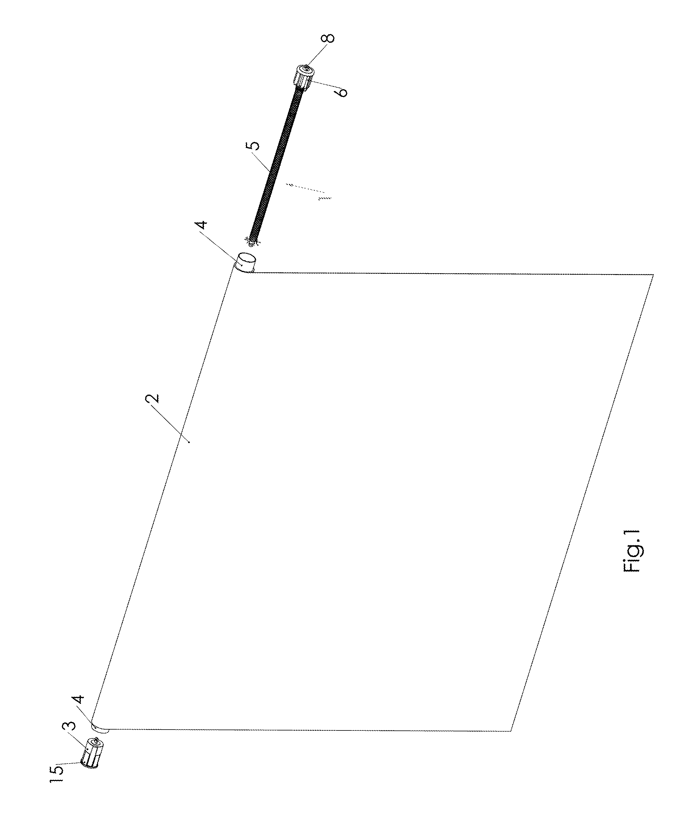
[0032]FIG. 1 presents generally the roller shade of the invention. The roller shade of the invention comprises at least such components as a shade 2, a tube-like shaft 4, a spring mechanism 1 and a brake 3.

[0033]The shade 2, which term here is used to describe the fabric part of the roller shade of e.g. cotton or polyester, can be wound or rolled around the shaft 4 in an upper position and be lowered in a lowered position. In FIG. 1, the shade 2 is partly wound up. The lower edge of the shade part 2 often has a bottom bar or some handle attached directly to the bar or a cord with a tassel to facilitate the lowering (not shown).

[0034]The spring mechanism 1, which in FIG. 1 is shown separately from the roller shade, is in reality inside the shaft 4 of the shade and it includes a rod 5 around which is fitted a spiral torsion spring (cannot be seen in FIG. 1). The spring is fixed with fastening means 6 that rotates with the shaft 4 and work as a bearing. The end of the rod 5 is availabl...

second embodiment

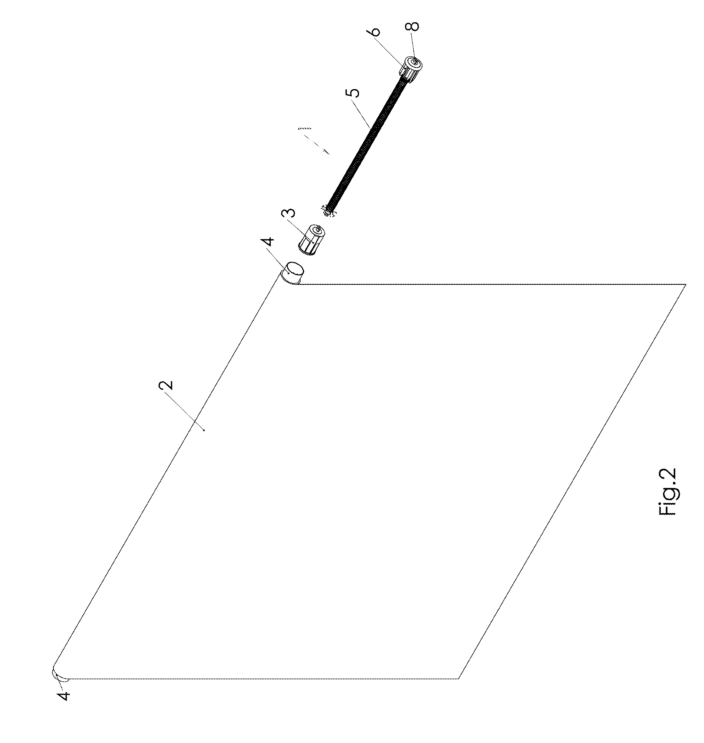
[0038]FIG. 2 presents generally the roller shade of the invention, wherein the spring mechanism 1 and the eddy current brake 3 are at the same end of the shaft 4 of the roller shade.

[0039]FIG. 3 is a detailed assembly illustration of the eddy current brake 3 used in the invention in parts. The eddy current brake 3 comprises a magnetic core 9 that consists of narrow perpendicularly magnetized discs 10 of permanent magnets glued around a first steel tube 11 being alternately placed with respect to their polarity (+up and down). The brake force can be adjusted by means of the length of the discs 10. The brake is more powerful the longer the discs 10 are. The magnetic force needed and the size of the magnets can be mathematically calculated when the force of the spring mechanism 1, the diameter of the shaft 4 and the desired raising speed of the shade is known.

[0040]There are slots 12 in both end of the first steel tube 11 to which round-shaped end plates 13, 14 of hard and slippery pla...


PUM


Abstract

The roller shade is wrapped around a shaft tube which has a supporting member through which the roller shade can be fastened to the wall or the like. The roller shade also includes a spring mechanism, with which the roller shade can be lowered upon tensioning of an un-wrap spring fitted around the shaft that rotates in a first direction at the lowering and be raised upon releasing of the un-wrap spring when the shaft rotates in the opposite direction. The roller shade is mainly characterized by an eddy current brake fastened to the shaft for a controlled release of the tensioning of the spring.

Description

TECHNICAL FIELD The invention is concerned with a roller shade that can be lowered upon tensioning of an un-wrap spring and raised upon releasing of the un-wrap spring.BACKGROUND[0001]Roller shades also called roller blinds are characterized by a lifting mechanism, with which the curtain part of the shade can be raised in an upper position and be lowered to a lower position. The most common type of lifting mechanism is a chain mechanism on one side of the shade. The chain mechanism includes a chain loop by means of which the roller shade can be wound up around a roll and be unwound again.[0002]Such chain loops as well as different ropes and strings can, however, cause a risk of choking for children that might place their head through the loop.[0003]Different accessories can be used to keep the ropes and strings unavailable for children or the minimizing of the risk can otherwise be taken into consideration in the product design.[0004]Such “safe by design” products are roller shades ...

Claims


Application Information

Patent Timeline
IPC IPC(8): E06B9/80E06B9/68E06B9/60
CPCE06B9/80E06B9/68E06B9/60E06B2009/807
Inventor POHJONEN, LASSE
Owner DOMICET
Why Eureka
Try Eureka