
Wire chopper module for EDM system

a wire chopper and edm technology, applied in the direction of electrical-based machining electrodes, manufacturing tools, grain treatment, etc., can solve the problems of inability to meet the needs of wire chopping, inability to fill the space available, and rapid wear of the tool edges used to section the wire, so as to reduce the cost of renewing the stationary cutting edge, avoid jamming, and increase the inertia. the effect of the momen

Inactive Publication Date: 2005-12-01
FLORIAN PRECISION
View PDF21 Cites 4 Cited by
  • Summary
  • Abstract
  • Description
  • Claims
  • Application Information

AI Technical Summary

Benefits of technology

[0011] Briefly stated, a preferred embodiment of the present invention comprises a wire chopper module in which both the stationary and rotating cutting tool edges used to shear spent EDM electrode are both repositionable and replaceable. Repositioning the cutting edges relative to the feed path of the spent electrode greatly extends the serviceable life of each cutting edge by permitting multiple uses of each edge. When all the available cutting edges are used, replacement of the cutting edges is easily accomplished in the field by replacement of an insert carrying the cutting edge. Thus, cutting edges can be renewed more frequently and with less expense, resulting in increased EDM system reliability.
[0014] In accordance with the present invention, one preferred embodiment of the anvil is configured as a square slab of carbide or hard material that is received in the anvil holder in any of eight positions to present eight new cutting edges before requiring replacement. The anvil is moveable relative to the wire guide orifice exit opening so that each of the eight cutting edges on the anvil can be used at least twice. As a result, a wire chopper module in accordance with the present invention can utilize the same anvil to present sixteen new cutting edges, greatly reducing the cost of renewing the stationary cutting edge in the inventive wire chopper module.
[0015] A wire chopper module in accordance with the present invention also include a flywheel mounted to the shaft to increase the moment of inertia of the rotating shaft and cutting inserts. This increased moment of inertial helps avoid jams that may occur when cutting surfaces become dull.
[0016] An object of the present invention is to provide a new and improved wire chopper module for an EDM system that permits renewal of both the rotating and stationary cutting edges without necessitating major disassembly or replacement of the wire chopper module.
[0017] Another object of the present invention is to provide a new and improved wire chopper module for an EDM system that reduces the cost and increases the reliability of EDM system operation.
[0018] A further object of the present invention is to reduce the cost and complexity associated with renewing the cutting edges of a wire chopper module for an EDM system.

Problems solved by technology

This approach proved unacceptable because the wire has a tendency for expansion in the reservoir.
This necessitates frequent intervention by the operator because the wire forms entanglements, which rapidly fill the space available in the reservoir.
A continuing problem with prior art wire-chopping devices is the rapid wear of the tool edges used to section the wire.
Chopping this wire results in high wear to cutting surfaces.
If cutting surfaces wear to the extent that the wire is no longer chopped cleanly, the wire-chopping device can jam resulting in a machine shutdown.
EDM systems frequently require a large capital investment, which motivates the owner to keep the machines in use as continuously as possible.
Failure of the electrode disposal device results in expensive downtime.
This results in high expense and the necessity to maintain an inventory of remanufactured and / or new wire-chopping devices.

Method used


Image

  • Wire chopper module for EDM system
  • Wire chopper module for EDM system
  • Wire chopper module for EDM system

Examples


Embodiment Construction

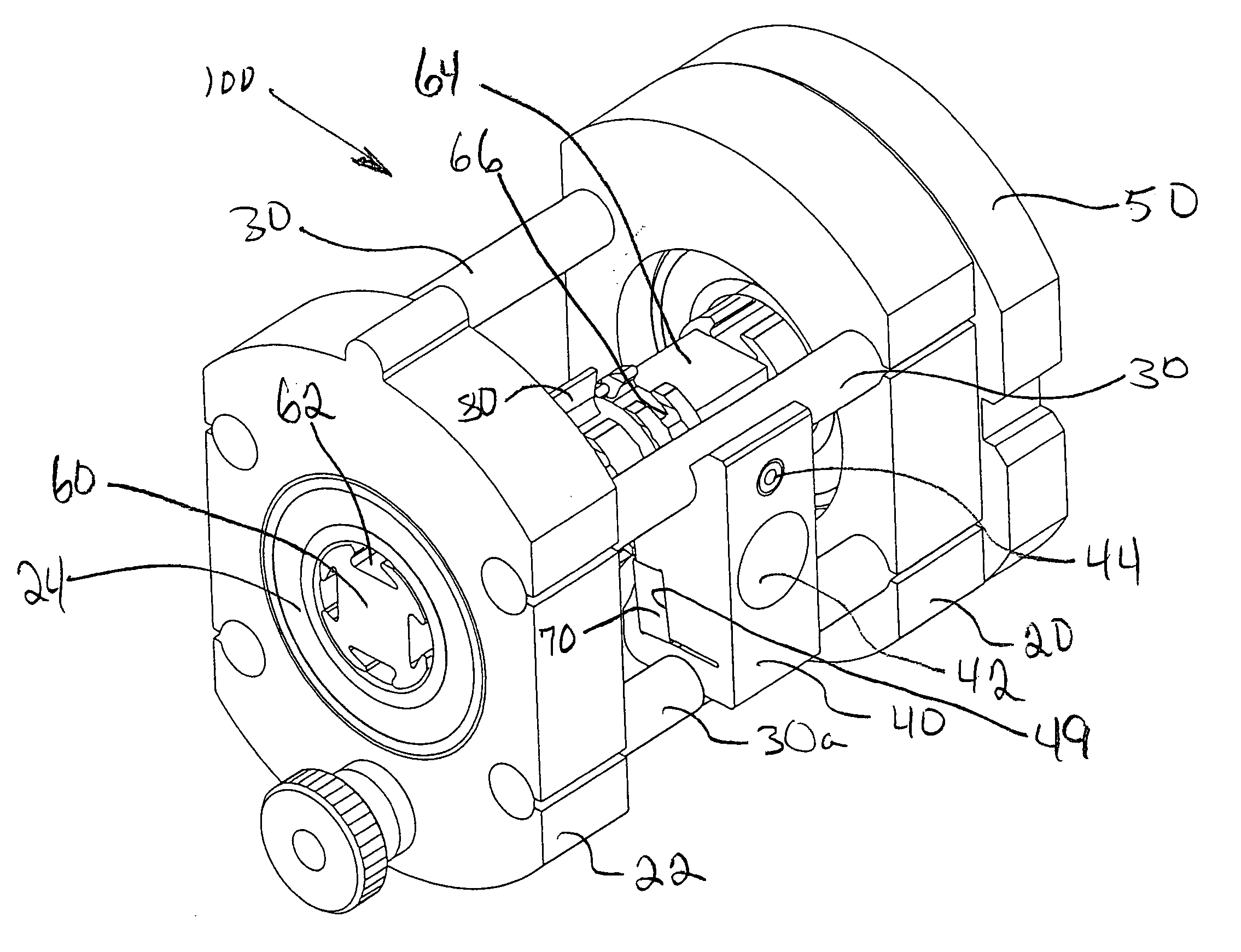
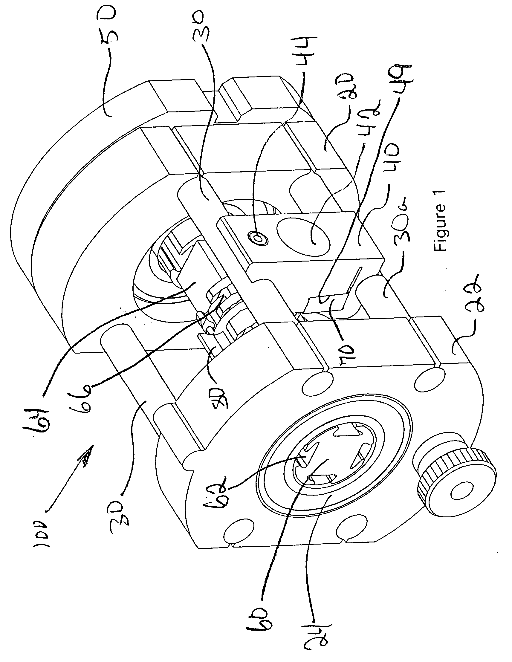
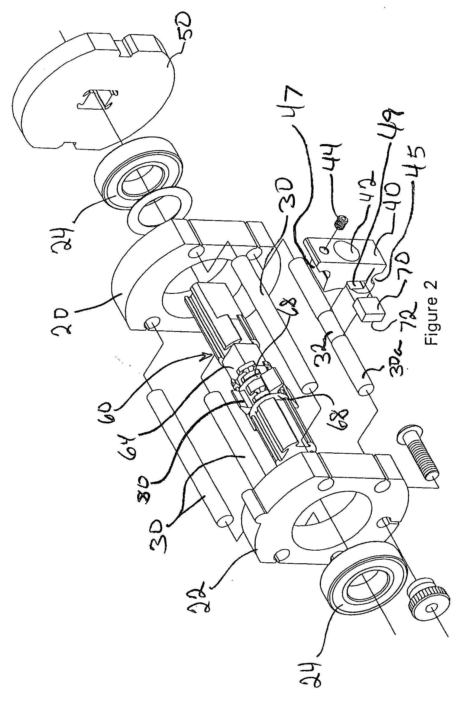
[0026] With reference to FIGS. 1-6, wherein like numbers refer to similar parts, one preferred embodiment of a wire chopper module in accordance with the present invention is illustrated in FIGS. 1-4. The wire chopper module 100 is inserted in the path of spent wire electrode exiting from an EDM system. The illustrated wire chopper module 100 comprises a frame assembled from a front end cap 22 and a rear end cap 20 that receive four body pins 30, 30a. Bearings 24 are received in each of the end caps 20, 22 to support the shaft 60 for rotation within the frame. In the illustrated embodiment, one of the body pins 30a defines an aid 32 for positioning an anvil holder 40.

[0027] The anvil holder 40 of the illustrated preferred embodiment 100 is mounted between two of the body pins 30, 30a. A lower semi-cylindrical cutout 45 on the anvil holder 40 is configured to fit over the body pin 30a at the positioning aid 32. The upper surface 47 of the anvil holder 40 is configured to slide under...


PUM

PropertyMeasurementUnit
circumferenceaaaaaaaaaa
electrical potentialaaaaaaaaaa
voltageaaaaaaaaaa

Abstract

A wire chopper module for processing spent electrode emerging from an EDM system employs replaceable inserts that are also movable relative to the feed path of the electrode. Shifting the position of the inserts relative to the feed path of the electrode allows more than one portion of each cutting edge on the insert to be used. Each insert has more than one cutting edge and can be rotated and re-inserted to present a completely new cutting edge. Removable multi-edge inserts that are repositionable relative to the feed path of the spent electrode permit renewal of the cutting edges of the wire chopper module with increased frequency and reduced cost. The wire chopper module also incorporates a flywheel to increase the movement of inertia of the rotating cutting inserts as an aid in overcoming jams. Sharp cutting edges and increased rotational momentum improve the reliability of the inventive wire chopper module.

Description

CROSS REFERENCE TO RELATED APPLICATIONS [0001] This application is a divisional of application Ser. No. 10 / 139,478, filed May 6, 2002.BACKGROUND OF THE INVENTION [0002] 1. Field of the Invention [0003] This invention generally relates to the processing of used electrode discharged from an electrical discharge machining (EDM) system and more particularly to a wire chopper module for shearing used electrode wire into many small pieces which accumulate in a relatively dense pile. [0004] 2. Description of the Related Art [0005] The process of electrical discharge machining (EDM) is well known. An electrical potential (voltage) is established between a continuously moving EDM electrode and an electrically conductive workpiece. The potential is raised to a level at which a discharge is created between the EDM electrode and the workpiece. The intense heat generated by the discharge will melt and / or vaporize a portion of both the workpiece and the electrode to thereby remove, in a very smal...

Claims


Application Information

Patent Timeline
Patent Type & Authority Applications(United States)
IPC IPC(8): B02C1/08B23D25/02B26D1/56
CPCB23H7/108Y10S83/955Y10S83/906Y10T83/9464Y10T83/9469Y10T83/4847
Inventor FLORIAN, DANA L.FLORIAN, KYLE B.
Owner FLORIAN PRECISION
Learn More