Camera-shooting terminal control method and device and camera-shooting terminal
A technology of terminal control and control method, which is applied in image communication, TV, color TV components and other directions, and can solve problems such as camera terminal control conflicts.
- Summary
- Abstract
- Description
- Claims
- Application Information
AI Technical Summary
Problems solved by technology
Method used
Image
Examples
Embodiment 1
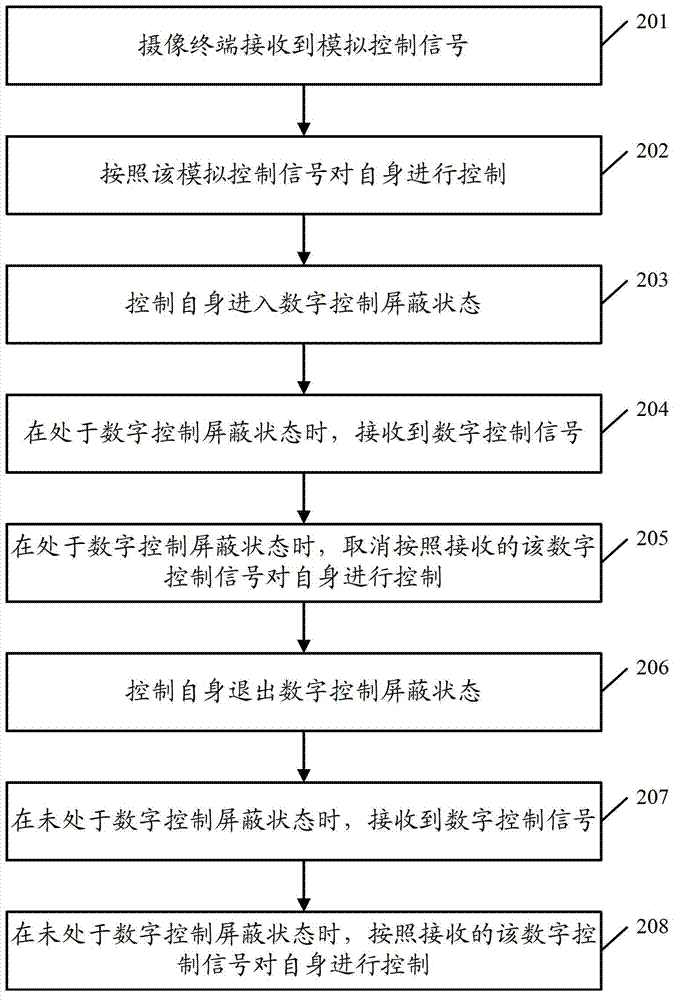
[0030] figure 2 Shown is a flow chart of the camera terminal control method provided by Embodiment 1 of the present invention, which specifically includes the following processing steps:
[0031] Step 201, the camera terminal receives the analog control signal sent by the analog monitoring terminal through the analog bus control mode.
[0032] Specifically, the camera terminal may determine that the analog control signal is received by monitoring the analog control serial port for receiving the analog control signal.
[0033] Wherein, the analog bus control may specifically be an analog 485 bus control, and the camera terminal may specifically be a spherical camera terminal widely used at present.
[0034] Step 202: After receiving the analog control signal, the camera terminal controls itself according to the analog control signal.
[0035] For example, it controls the opening and closing of its own camera, and the camera angle.
[0036] Step 203: After receiving the anal...
Embodiment 2
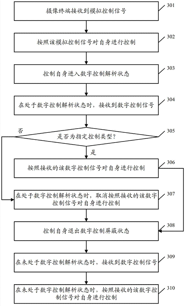
[0048] image 3 Shown is a flow chart of the camera terminal control method provided by Embodiment 2 of the present invention, which specifically includes the following processing steps:
[0049] Step 301, the camera terminal receives the analog control signal sent by the analog monitoring terminal through the analog bus control mode.
[0050] Specifically, the camera terminal may determine that the analog control signal is received by monitoring the analog control serial port for receiving the analog control signal.
[0051]Wherein, the analog bus control may specifically be an analog 485 bus control, and the camera terminal may specifically be a spherical camera terminal widely used at present.
[0052] Step 302: After receiving the analog control signal, the camera terminal controls itself according to the analog control signal.
[0053] For example, it controls the opening and closing of its own camera, and the camera angle.
[0054] Step 303: After receiving the analog...
Embodiment 3
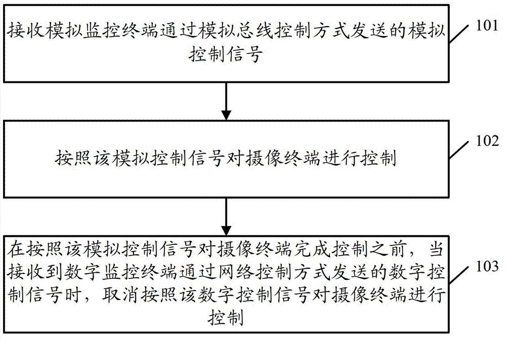
[0071] Based on the same inventive concept, according to the video camera terminal monitoring method provided by the above-mentioned embodiments of the present invention, correspondingly, Embodiment 3 of the present invention also provides a camera terminal monitoring device, the structural diagram of which is as follows Figure 4 shown, including:
[0072] The receiving unit 401 is used to receive the analog control signal sent by the analog monitoring terminal through the analog bus control mode;
[0073] An analog control unit 402, configured to control the camera terminal according to the analog control signal;
[0074] The digital control unit 403 is configured to, before the analog control unit 402 completes the control of the camera terminal according to the analog control signal, when receiving the digital control signal sent by the digital monitoring terminal through the network control mode, cancel the control according to the digital control. The signal controls th...
PUM
 Abstract
Description
Claims
Application Information
 - R&D
- Intellectual Property
- Life Sciences
- Materials
- Tech Scout
- Unparalleled Data Quality
- Higher Quality Content
- 60% Fewer Hallucinations
Browse by: Latest US Patents, China's latest patents, Technical Efficacy Thesaurus, Application Domain, Technology Topic, Popular Technical Reports.
© 2025 PatSnap. All rights reserved.Legal|Privacy policy|Modern Slavery Act Transparency Statement|Sitemap|About US| Contact US: help@patsnap.com


