Panorama splicing linkage method and device based on moving target detecting

A moving target, panoramic technology, applied in the field of video processing, can solve the problems of tracking failure, target switching, long target distance, etc., to achieve the effect of reducing workload, avoiding back and forth switching, and high resolution

Active Publication Date: 2014-04-09
SHENZHEN INFINOVA
View PDF10 Cites 77 Cited by
  • Summary
  • Abstract
  • Description
  • Claims
  • Application Information

AI Technical Summary

Problems solved by technology

[0003] So far, there are two types of common monitoring equipment. The first is the trigger, which is aimed at a certain scene for monitoring. The disadvantage is that when there are many monitoring scenes, it is necessary to switch back and forth between each scene. When there are many channels and frequent switching, the monitoring personnel will get tired easily, and people's attention can only be concentrated on part of the screen; The field of view of the camera is limited, and only one scene can be monitored at the same time, so some important information will still be missed
[0004] In the target tracking process, if you rely solely on the dome camera, the tracking effect is affected by many factors, whether it is through manual ball control or automatic tracking of the target, and it is prone to tracking failure or target switching. Near the target, it is easy to miss other important information
If relying on the gun, the target is likely to appear in multiple screens, and the switching between screens will affect the capture of video information by the surveillance personnel, and the installation direction of the gun is fixed, the monitoring scene will not change with the target, and it is easy to lose the tracking target
And in video surveillance, often due to the long distance of the target, the accuracy of detection and recognition of the target (face, license plate, etc.) is low

Method used


Image

  • Panorama splicing linkage method and device based on moving target detecting
  • Panorama splicing linkage method and device based on moving target detecting
  • Panorama splicing linkage method and device based on moving target detecting

Examples


Embodiment 1

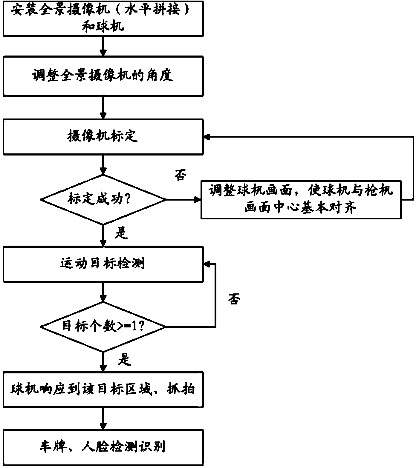
[0126] The method of this embodiment is as image 3 as shown,

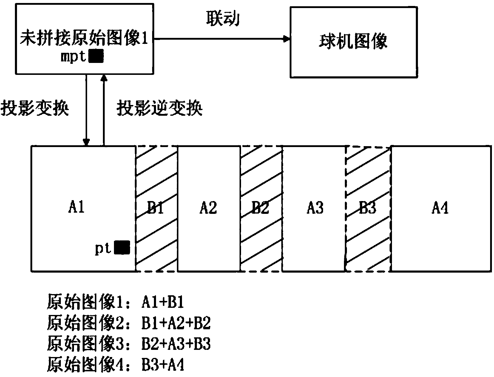
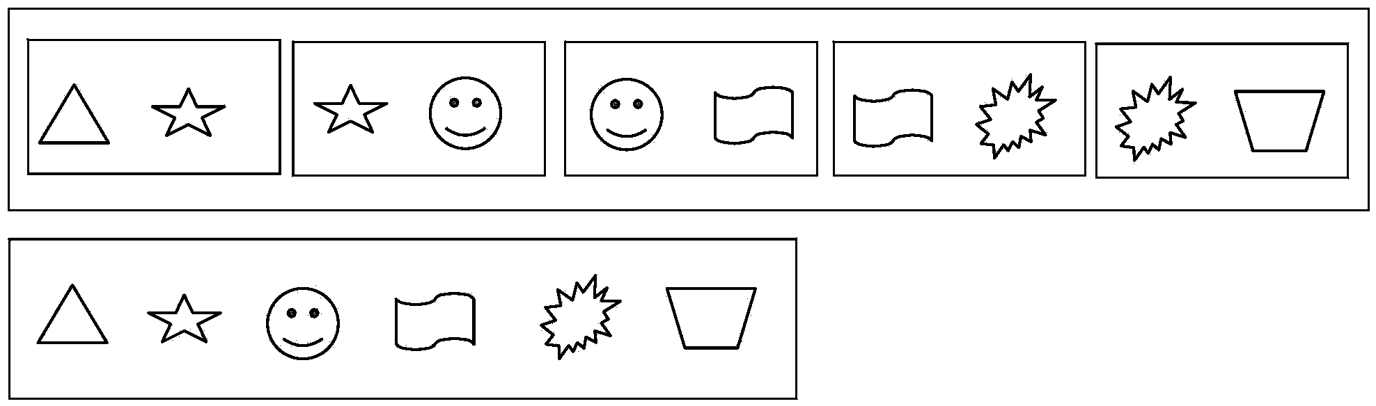
[0127] A) During the camera installation process, the panoramic stitching camera adopts a horizontal stitching method. During the installation process, there is a partial overlapping area between the pictures of the panoramic stitching camera, so try to stitch them together. If the stitching is unsuccessful, adjust the lenses of the panoramic stitching camera direction, increase the overlap until panoramic image stitching can be realized. The resulting panorama is figure 2 As shown in , it is a strip-shaped panoramic picture composed of multiple individual pictures spliced ​​along the horizontal direction.

[0128] B) Adjust the field of view of the panoramic stitching camera so that the field of view in the panoramic stitching screen can be covered by the dome camera.

[0129] C), camera calibration, establishing the mapping relationship between the position of the dome camera and the panoramic stitching came...

Embodiment 2

[0136] The method of this embodiment is as Figure 5 as shown,

[0137] A) During the camera installation process, the panoramic splicing camera adopts a vertical splicing method. During the installation process, there is a partial overlapping area between the pictures of the panoramic splicing camera, so as to try splicing. If the splicing is unsuccessful, adjust each lens of the panoramic splicing camera direction, increase the overlap until panoramic image stitching can be achieved. The resulting panorama is Figure 4 As shown in , it is a strip-shaped panoramic picture formed by splicing multiple separate pictures along the vertical direction.

[0138] B). Adjust the field of view of the panoramic stitching camera so that most of the field of view in the panoramic stitching screen can be covered by the dome camera.

[0139] C), camera calibration, establishing the mapping relationship between the position of the dome camera and the panoramic stitching camera;

[0140] ...

Embodiment 3

[0145] The method of this embodiment is as Figure 7 as shown,

[0146] A) During the camera installation process, the panoramic splicing camera adopts the horizontal and vertical splicing method. During the installation process, there is a partial overlapping area between the pictures of the panoramic splicing camera, so as to try splicing. If the splicing is unsuccessful, adjust each of the panoramic splicing cameras. Lens direction, increase the overlap until panoramic image stitching can be realized. The resulting panorama is Figure 6 As shown in FIG. 1 , a large scene panorama picture is composed of a plurality of individual grid-distributed pictures spliced ​​along the horizontal and vertical directions.

[0147] B). Adjust the field of view of the panoramic stitching camera so that most of the field of view in the panoramic stitching screen can be covered by the dome camera.

[0148] C), camera calibration, establish the mapping relationship between the position of ...


PUM


Abstract

The invention provides a panorama splicing linkage method and device based on moving target detecting. A large-view panorama image is obtained by panorama splicing, then view is adjusted, the position mapping relation of a ball machine and a panorama splicing video camera is established, then moving target detecting is carried out on an area of interest in the panorama image, after a moving target is detected, the corresponding ball machine is automatically triggered to track the target of the area of interest according to the mapping relation to achieve linkage, accordingly, the problem that the moving target (a human face, a license plate and the like) in the panorama image cannot be seen clearly under the situation of long distance is avoided, workload of monitoring personnel is reduced, a complete, large-view, and high-resolution continuous image is provided for an operator, the observing angle is similar to the view angle of a human eye, and switching back and forth between images during monitoring is avoided.

Description

technical field [0001] The present invention relates to the technical field of video processing, in particular to a panorama splicing linkage method and device based on moving object detection. Background technique [0002] Today, with the rapid development of the monitoring system, the scale of the system is getting bigger and bigger, and there are more and more monitoring points. The staff have no time to take care of more and more monitoring images. With the continuous expansion of the monitoring range, it is necessary to monitor the entire bridge. , Airports, a long section of road or high-rise buildings are monitored, and the field of view of most cameras cannot reach such a large monitoring range. Therefore, the requirements for video surveillance with a large field of view are gradually increasing, and a high-end demand has gradually formed. As a solution, panoramic video stitching has also received more and more attention. The accompanying video surveillance system ...

Claims


Application Information

Patent Timeline
Patent Type & Authority Applications(China)
IPC IPC(8): H04N7/18H04N5/232G06T7/00G06T7/20
Inventor 魏园波彭俊林小晖周玉龙
Owner SHENZHEN INFINOVA
Why Eureka
Try Eureka