Endoscope

A technology for endoscopes and ring-shaped components, which is applied in the field of endoscopes, can solve the problems of uneven bonding state, the rotation amount adjustment mechanism of C-ring components does not work very well, and cannot obtain traction, etc., to achieve strong The effect of traction

Inactive Publication Date: 2014-04-09
OLYMPUS CORP
View PDF10 Cites 5 Cited by
  • Summary
  • Abstract
  • Description
  • Claims
  • Application Information

AI Technical Summary

Problems solved by technology

[0009] However, in the conventional endoscopes disclosed in JP-A-2003-325437 and JP-A-2009-5836, etc., as a means for obtaining a stronger pulling force, there is a problem that even if the Only by increasing the winding angle of the pulling wire to the C-ring, sometimes the rotation amount adjustment mechanism of the C-ring does not function well, and sometimes the necessary pulling force cannot be obtained.
As a result, the annular member is deformed, and the close contact state between the inner surface of the annular member and the outer peripheral surface of the pulley is not uniform, and it may be difficult to obtain sufficient resistance.

Method used


Image

  • Endoscope
  • Endoscope
  • Endoscope

Examples


no. 1 Embodiment approach

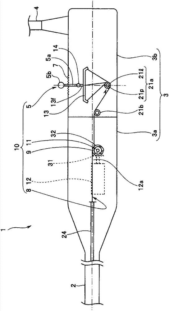
[0102] Figure 1 to Figure 8 It is a figure which shows 1st Embodiment of this invention.

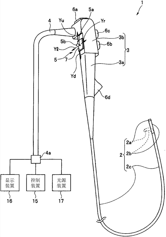
[0103] First, below, the main use figure 1 The overall configuration of an endoscope system including the endoscope according to the first embodiment of the present invention will be described.

[0104] An endoscope system including the endoscope 1 of the present embodiment is mainly composed of the endoscope 1, a control device 15, a display device 16, a light source device 17, and the like.

[0105] The endoscope 1 is composed of an elongated tubular insertion portion 2 , an operation portion 3 continuously provided on the proximal end side of the insertion portion 2 , a universal cable 4 extending from the side of the operation portion 3 , and the like.

[0106] The insertion part 2 is composed of a front end part 2a, a bending part 2b configured to be bendable in vertical, left and right directions, and a flexible flexible tube part 2c formed in an elongated shape, in order from ...

no. 2 Embodiment approach

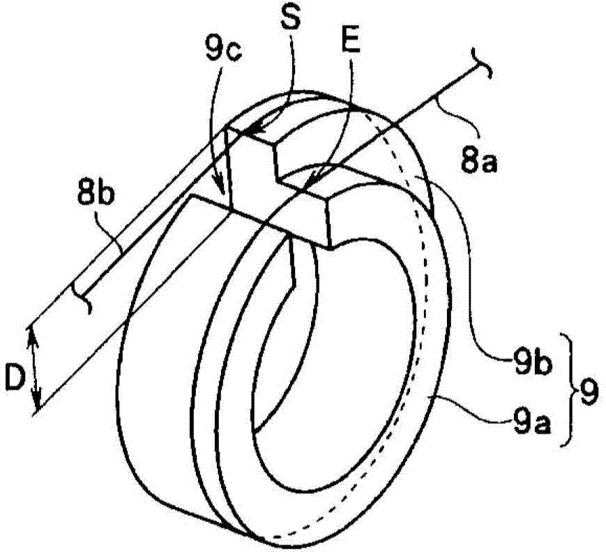
[0170] Figure 9 ~ Figure 11 It is a figure which shows 2nd Embodiment of this invention.

[0171] The basic configuration of this embodiment is substantially the same as that of the above-mentioned first embodiment, and the only difference from the first embodiment lies in the structures of the C-ring member and the pulling member in the pulling member operating device. Therefore, in the following description, the same reference numerals are attached to the same structures as those of the above-mentioned first embodiment, their descriptions are omitted, and only different structures will be described in detail.

[0172] Such as Figure 9 , Figure 10 As shown, the C-ring member 9A in the traction member operating device of the endoscope 1A according to this embodiment is formed in such a manner that two C-ring members having different outer diameters and partially having a cutout 9Ac are superimposed on the same axis. That is, the operating wire extending portion 9Aa and t...

no. 3 Embodiment approach

[0179] Figure 12 to Figure 14 It is a figure which shows 3rd Embodiment of this invention.

[0180] The basic structure of this embodiment is substantially the same as that of the above-mentioned first embodiment, and the difference from the first embodiment is only the structure of the C-ring member in the traction member operating device. Therefore, in the following description, the same reference numerals are attached to the same structures as those of the above-mentioned first embodiment, their descriptions are omitted, and only different structures will be described in detail.

[0181] Such as Figure 12 , Figure 13 As shown, the C-ring member 9B in the traction member operating device of the endoscope 1B according to this embodiment is constituted by a single C-ring member partially having a notch 9Bc. Therefore, the C-ring member 9B of this embodiment is different from the C-ring members 9 and 9A in the above-mentioned first and second embodiments in that the opera...


PUM


Abstract

The purpose of the present invention is to provide an endoscope that efficiently and reliably achieves a stronger pulling force. The endoscope is thus provided with: a drive part (12) that generates a drive force that bends a bending section (2b); a C-ring-shaped member (9) that is capable of frictionally engaging with a pulley (11), and has a notched section (9c) in part of the ring-shaped member; an operation input member (5) that performs a bending operation on the bending section (2b); an operation input-side pulling member (8a) that serves as a first pulling member that winds around the C-ring-shaped member and extends from the C-ring-shaped member toward the operation input member, and is connected to the operation input member in such a manner as to straddle the notched section from a position extending toward the operation input member of the C-ring-shaped member and coil around the C-ring-shaped member such that the coiling around distance decreases with an increase in the operation amount of the operation input member; and a bending section-side pulling member (8b) that serves as a second pulling member that winds around the C-ring-shaped member and extends from the C-ring-shaped member toward the bending section, and is connected to the bending section in such a manner as to straddle the notched section from a position that extends toward the bending section on the C-ring-shaped member without coiling around the C-ring-shaped member.

Description

technical field [0001] The present invention relates to an endoscope that can receive assistance from the driving force of a drive unit to move the traction member provided on the operation part by performing a tilting operation to change the tilting direction and tilting angle of the operation member provided on the operation part. The upper bending part performs the bending operation. Background technique [0002] In recent years, endoscopes having elongated insertion portions have been used in the medical and industrial fields. In an endoscope in the medical field, observation and the like can be performed by inserting an insertion portion into the body from the oral cavity, anus, or the like. On the other hand, in an endoscope in the industrial field, it is possible to perform observation or the like by inserting an insertion portion into a pipe of mechanical equipment such as a boiler or inside an engine. [0003] Generally, in an endoscope, an observation optical sys...

Claims


Application Information

Patent Timeline
Patent Type & Authority Applications(China)
IPC IPC(8): A61B1/00
CPCA61B1/0052A61B1/0057A61B1/0016A61B1/00042
Inventor 冈本康弘
Owner OLYMPUS CORP
Why Eureka
Try Eureka