System for handling equipments for the drilling of the ground

a technology for handling equipment and drilling equipment, applied in earth drilling and mining, feeding apparatus, drilling machines and methods, etc., can solve the problems of affecting the drilling effect, so as to achieve high handling speed, strong traction, and optimal yield

Active Publication Date: 2011-07-21
SOILMEC
View PDF10 Cites 2 Cited by
  • Summary
  • Abstract
  • Description
  • Claims
  • Application Information

AI Technical Summary

Benefits of technology

The aim of the present invention is therefore to describe a handling system for ground drilling tools, which has none of the drawbacks described above and permits to obtain strong tractions, high handling speeds, optimal yields, the possibility to actuate the handling forces in any position of the antenna, by exploiting the whole stroke present and thanks to its simplicity, with reduced times of transformation for the conversion from one technology to the other.

Problems solved by technology

This fact causes a relevant difficulty in designing the carpentry and a distribution of the weights housed in very high positions, with a consequent arising of the centre of gravity of the machine, damaging its stability and with more difficulties in lifting the tower in case of self-lifting tools.
The presence of a plurality of pulleys causes a loss of efficiency and the actual traction becomes greatly lower than the nominal one.
Practically, the handling system of the cylinder type, despite its simplicity, provides strokes and extraction speeds lower than the system of the rope type.
Also, the machine conversion needed to pass from one technology to the other requires long transformation times, especially if it is performed in a yard.
The system, despite the fact that it permits to obtain relevant speeds (maximum values around 35 m / min) is limited to traction or pushing forces slightly greater than 10 t, which are not sufficient to satisfy all the digging technologies.

Method used


Image

  • System for handling equipments for the drilling of the ground
  • System for handling equipments for the drilling of the ground
  • System for handling equipments for the drilling of the ground

Examples


fourth embodiment

In such a case, the handling system is configured in use, represented in FIG. 8.

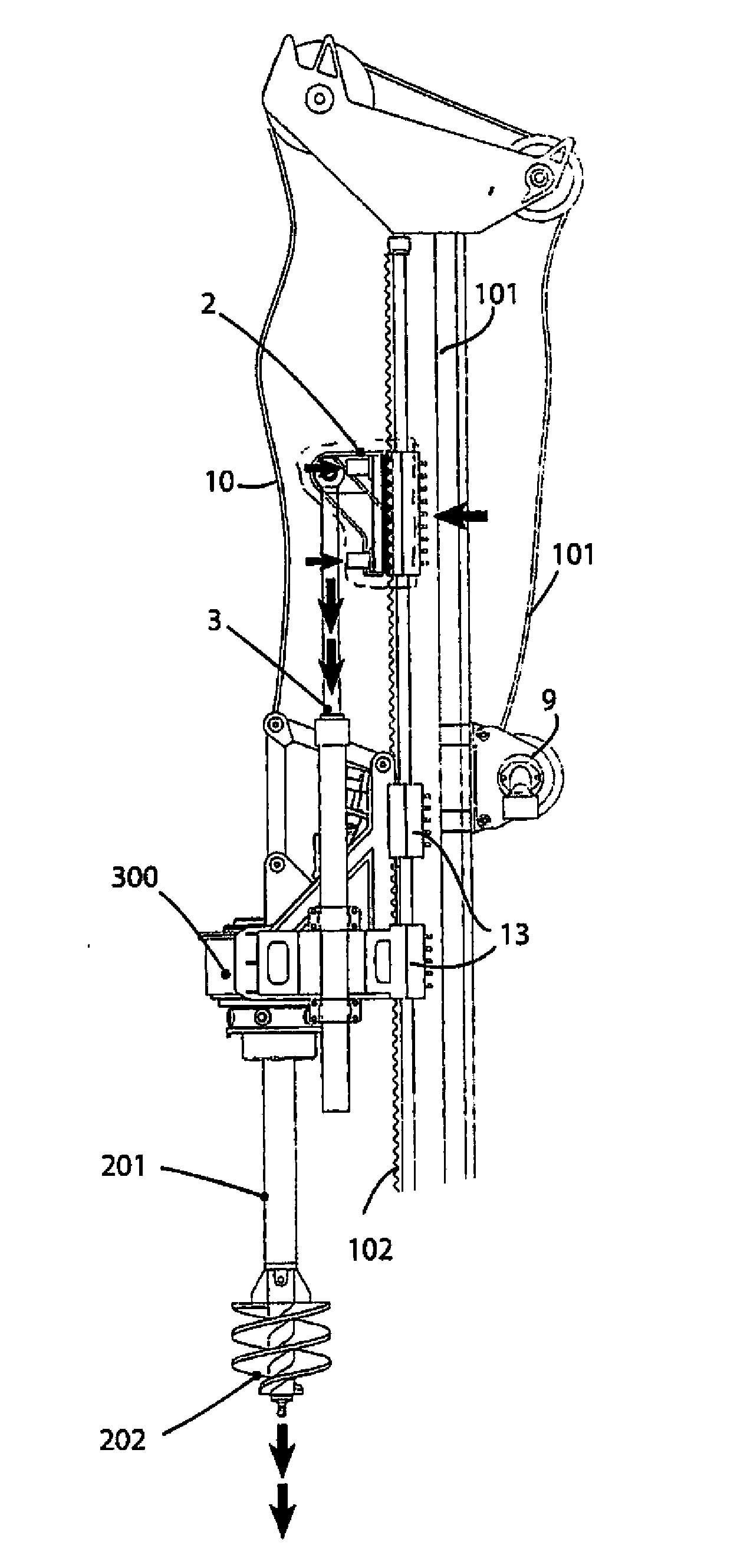
In such an embodiment of use, in order to assist the traction force applied by winch 9 tensioning rope 10 by integrally forcing digging equipment 200 with power assembly 300 to lift towards the top of tower 101, also cylinder 3 is used.

In this case first of all blocking jacks 5 extend by engaging again toothed element 6 against rack 102, so linking element 2 to tower 101 in a rigid way; so cylinder 3 extends by applying a resistance between element 2 and power assembly 300 pushing the same upwards, together with digging equipment 200, in a direction opposite to the ground and so it assists its exit from the hole.

Obviously, if the second embodiment of the handling system according to the present invention is used, cylinder 3 does not extend but it will retract, because element 2 is placed above power assembly 300 in such an embodiment.

Therefore, in the second embodiment the force applied by hydraulic cyli...


PUM


Abstract

A handling system (1″) is for drilling equipment (200) of the ground, in which the drilling equipment (200) slides along a support tower (101, 501) fixed or movable with respect to the ground. The handling system (1″) includes at least one linear actuator (3, 3a, 3b) for handling the digging equipment. The linear actuator (3, 3a, 3b) being temporarily movable and releasable with respect to the tower (101, 501).

Description

This application is claims benefit of Serial No. TO2009A001021, filed 22 Dec. 2009 in Italy and which application is incorporated herein by reference. To the extent appropriate, a claim of priority is made to the above disclosed application.BACKGROUNDThe present invention relates to the field of drilling technologies, and to a system for handling equipments for the drilling of the ground.It is known that the procedures for realizing a digging of the foundation, for consolidation or for drainage of the ground refer with an absolute priority to a tower machine comprising a power assembly and means for drilling and means for digging the ground; said tower being delimited in its upper part by a head and in its lower part by a foot and the power assembly (hydraulic or electric) moves along the over-said tower between the head and the foot, by transmitting the rotary motion and an advancement or lift force to the digging means.During the course of time, the increasing of power in internal...

Claims


Application Information

Patent Timeline
Patent Type & Authority Applications(United States)
IPC IPC(8): B23Q5/22
CPCE21B7/02E21B19/086E21B19/084
Inventor BISERNA, EZIO
Owner SOILMEC
Why Eureka
Try Eureka