

Cover body for battery case
A technology of a battery box and a cover body is applied in the field of cover bodies for battery boxes, which can solve the problems of cracking of the safety valve 5 and achieve the effect of reliable cracking.
- Summary
- Abstract
- Description
- Claims
- Application Information
AI Technical Summary
Problems solved by technology
Method used
Image

Examples
Embodiment approach 1
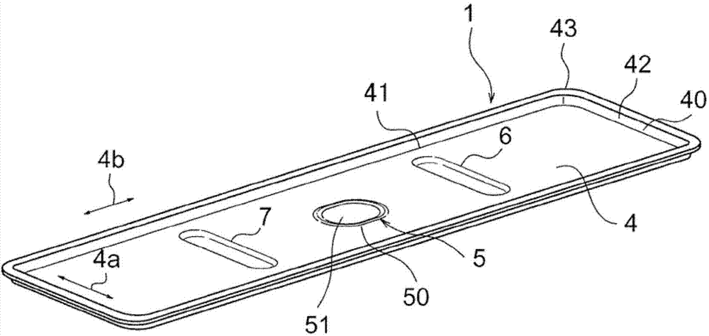
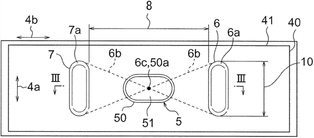
[0027] figure 1 It is a perspective view showing the cover body 1 for the battery box 3 according to Embodiment 1 of the present invention, figure 2 yes means figure 1 A top view of the cover body 1, image 3 is along figure 2 Cross-sectional view of line III-III. In addition, the same reference numerals are used for the conventional battery box cover (refer to Figure 8 as well as Figure 9 ) to describe the same or equivalent parts. figure 1 The shown cover body 1 and the bottomed cylindrical box main body 2 (refer to Figure 8 ) constitute together, for example, a battery case 3 for accommodating an electrolyte in a battery such as a lithium-ion battery (refer to Figure 8 ). The entire cover body 1 is made of a metal plate made of stainless steel.
[0028] The lid body 1 has a lid body body 4 , a safety valve 5 , and a pair of ribs 6 , 7 . Such as figure 2 As shown, the cover main body 4 is a substantially planar flat plate portion formed in a rectangular sha...
Embodiment approach 2
[0064] Figure 5 It is a top view showing the battery box cover body 1 according to Embodiment 2 of the present invention. In Embodiment 1, it was explained that the intersection point 6c of the two line segments 6b connecting the ends of the ribs 6 and 7 is arranged so as to coincide with the center position 50a of the annular thin-walled portion 50 (see figure 2 ), however, in Embodiment 2, the annular thin-walled portion 50 is arranged so that the intersection point 6c of the line segment 6b is received in the inner peripheral region of the annular thin-walled portion 50, and the central position 50a of the annular thin-walled portion 50 offset. In addition, the inner peripheral region of the annular thin-walled portion 50 refers to a region including not only the inner side of the annular thin-walled portion 50 but also the annular thin-walled portion 50 itself. Other structures are the same as those in Embodiment 1.
[0065] Next, the function will be described. In c...
Embodiment approach 3
[0070] Figure 6 It is a top view showing the battery box cover 1 according to Embodiment 3 of the present invention. In Embodiments 1 and 2, the ribs 6 and 7 are provided so as to be completely along the short-dimension direction 4a of the cover main body 4, but as long as the respective ribs 6 and 7 extend along the short-dimension direction 4a as a whole, Can also be formed into other shapes, for example, as Figure 6 As shown, the longitudinal direction of each rib 6 , 7 may be formed to be inclined with respect to the short direction 4 a of the cover main body 4 .
[0071] In this way, even if the ribs 6, 7 are not provided completely along the short dimension direction 4a of the cover main body 4, as long as the ribs 6, 7 extend along the short dimension direction 4a as a whole, each rib can be The portions 6 and 7 have rigidity against deformation of the lid main body 4 when the internal pressure of the tank increases. As a result, since the deformation of the periph...
PUM
 Abstract
Description
Claims
Application Information