Liquid ejection head and manufacturing method thereof

a technology of liquid ejection head and manufacturing method, which is applied in the field of liquid, can solve the problems of substrates' susceptibility to cracking, the shape of the side surfaces of the reservoir portion is difficult to accurately control through the correction pattern, and the increase in cost, and achieves the effect of highly accurate formation

Active Publication Date: 2009-08-20
SEIKO EPSON CORP
View PDF0 Cites 0 Cited by
  • Summary
  • Abstract
  • Description
  • Claims
  • Application Information

AI Technical Summary

Benefits of technology

[0014]An advantage of some aspects of the invention is that a liquid ejection head in which substrate cracking can be prevent...

Problems solved by technology

If the width of the break pattern is large, the number of flow channel-forming substrates or the reservoir-forming substrates that can be formed on one silicon wafer decreases, resulting in an increase in cost.
However, the shape of the side surfaces of the reservoir portion is difficult ...

Method used


Image

  • Liquid ejection head and manufacturing method thereof
  • Liquid ejection head and manufacturing method thereof
  • Liquid ejection head and manufacturing method thereof

Examples


Embodiment Construction

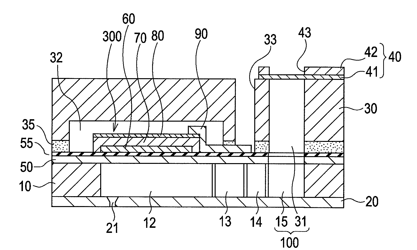
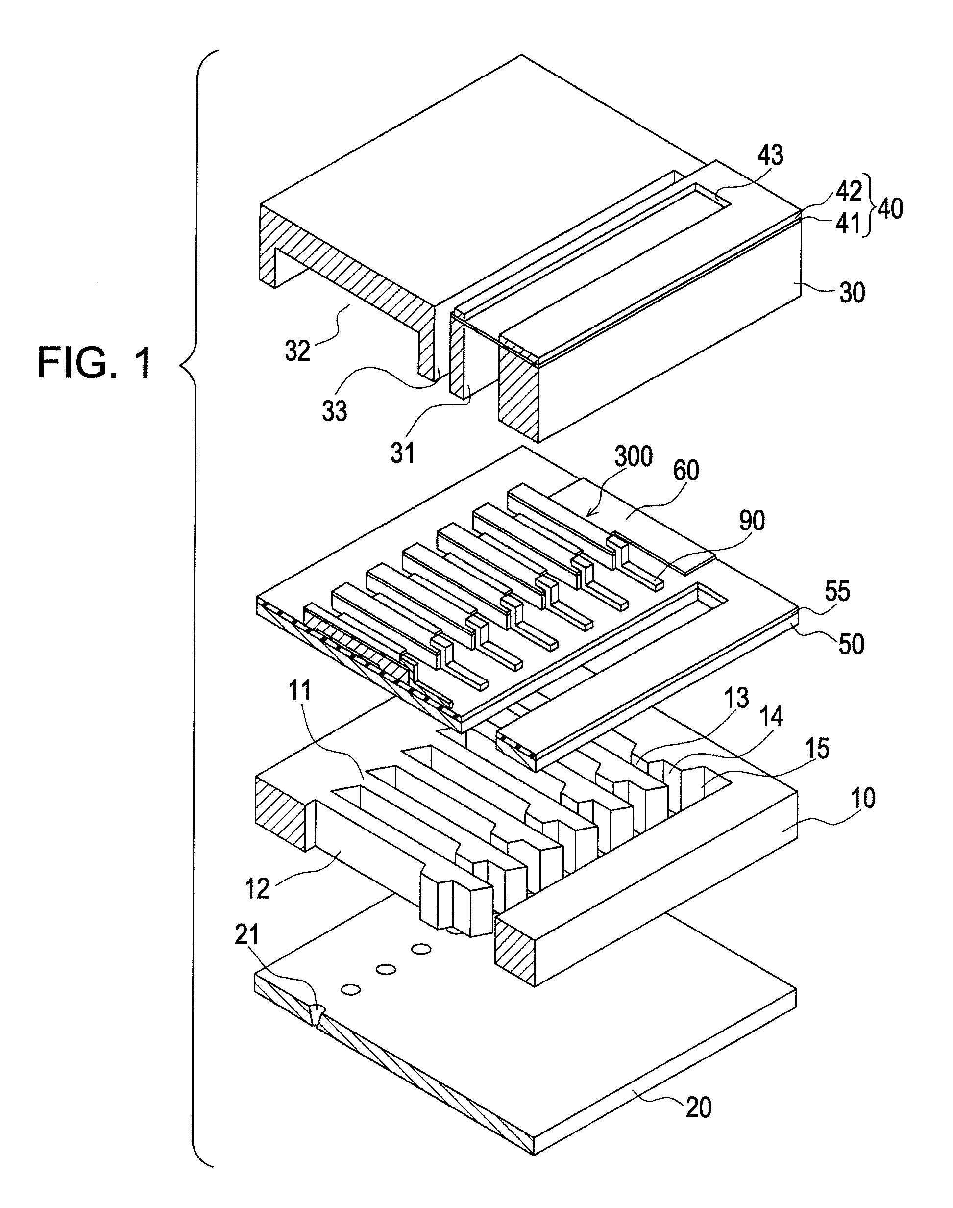
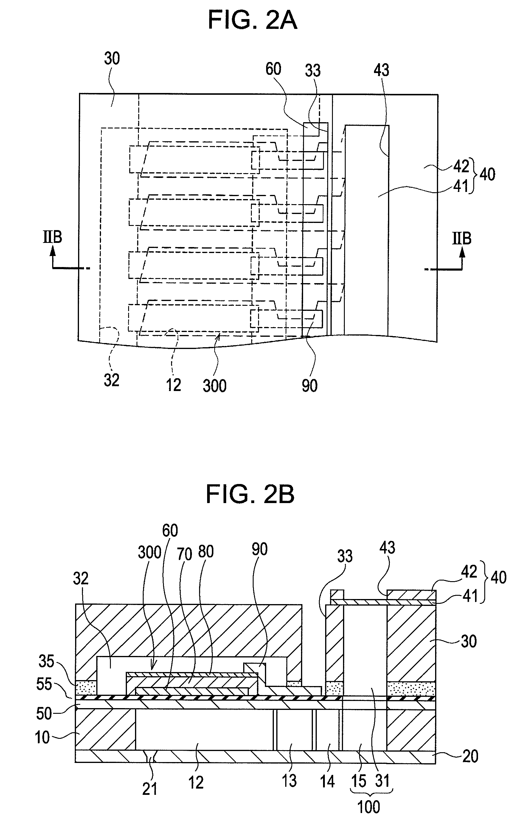
[0032]Embodiments of the invention will now be described in detail. FIG. 1 is an exploded perspective view of an ink jet recording head manufactured by a method according to one embodiment of the invention. FIG. 2A is a partial plan view of the recording head shown in FIG. 1, and FIG. 2B is a cross-sectional view taken along line IIB-IIB of FIG. 2A. FIG. 3 is a plan view of a flow channel-forming substrate. FIG. 4 is a plan view of a reservoir-forming substrate.

[0033]A flow channel-forming substrate 10 is a silicon single crystal substrate having a (110) plane orientation. An elastic film 50 made of an oxide film is formed on one surface of the flow channel-forming substrate 10, as shown in the drawing. The flow channel-forming substrate 10 has a plurality of pressure-generating chambers 12 defined by dividing walls 11. The pressure-generating chambers 12 are arranged parallel to each other in the width direction (transverse direction) of the flow channel-forming substrate 10. The d...


PUM


Abstract

A liquid ejection head includes a flow channel-forming substrate having a plurality of pressure-generating chambers communicated with nozzles configured to eject droplets, the plurality of pressure-generating chambers being arranged in parallel with each other; a plurality of pressure-applying units configured to apply pressure to interiors of the pressure-generating chambers; and a joining substrate joined onto one surface of the flow channel-forming substrate. The flow channel-forming substrate includes a silicon single crystal substrate having a (110) plane orientation and has a side surface extending in a longitudinal direction of the pressure-generating chambers, the side surface being composed of a first (111) plane perpendicular to a (110) plane. The joining substrate includes a silicon single crystal substrate having a (110) plane orientation and is joined onto the flow channel-forming substrate so that a first (111) plane of the joining substrate perpendicular to the (110) plane intersects the first (111) plane of the flow channel-forming substrate.

Description

BACKGROUND[0001]1. Technical Field[0002]The present invention generally relates to liquid ejection heads that eject droplets from nozzles and methods of manufacturing the liquid ejection heads. In particular, the invention relates to an ink jet recording head that ejects ink droplets and a method of manufacturing the ink jet recording head.[0003]2. Related Art[0004]An ink jet recording head that ejects ink droplets is a representative example of a liquid ejection head that ejects droplets. One example of the ink jet recording head includes a nozzle plate with nozzles perforated therein, a flow channel-forming substrate in which a plurality of pressure-generating chambers communicated with the nozzles are formed, a piezoelectric element serving as a pressure-generating unit and being disposed at one side of the flow channel-forming substrate, and a reservoir-forming substrate (protective substrate) having a reservoir portion communicated with the plurality of pressure-generating cham...

Claims


Application Information

Patent Timeline
IPC IPC(8): B41J2/045
CPCB41J2/14233B41J2/1634B41J2/1632B41J2/161B41J2/1635B41J2/1629
Inventor MIYATA, YOSHINAO
Owner SEIKO EPSON CORP
Why Eureka
Try Eureka