Illumination optical system, exposure method and designing method

Inactive Publication Date: 2008-02-07
FUJITSU SEMICON LTD
View PDF4 Cites 59 Cited by
  • Summary
  • Abstract
  • Description
  • Claims
  • Application Information

AI Technical Summary

Benefits of technology

[0013]The present invention is made in view of the above described problems, and has an object to provide an illumination optical system, an aligner, an exposure method and a designing method with high reliability, which correspond to exposure for performing patterning in which microp

Problems solved by technology

An alternating phase shift mask makes desired microfabrication possible with an extremely wide margin as described above, but on the other hand, it has the problems that its manufacturing process is complicated and manufacture cost is high.
The problem of the three-dimensional structure of the alternating phase shift mask cannot be treated lightly.
However, if miniaturization of processing dimensions advances, and the light shield film becomes small, this is expected to be a large pro

Method used


Image

  • Illumination optical system, exposure method and designing method
  • Illumination optical system, exposure method and designing method
  • Illumination optical system, exposure method and designing method

Examples


Embodiment Construction

[0040]—Basic Gist of the Present Invention—

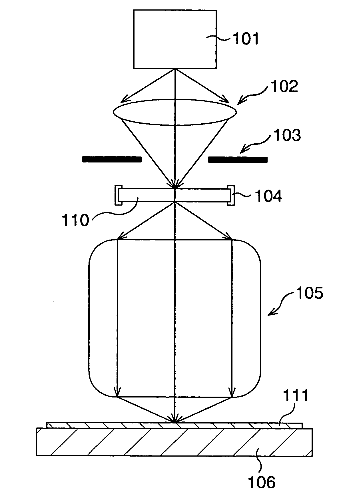
[0041]In order to realize light irradiation corresponding to various patterns by one exposure, the present invention presents an illumination optical system including an illumination control mechanism which adjusts a light intensity distribution of irradiation light which is irradiated to an irradiation object (phosomask) to be in an illumination state in which a plurality of double pole illuminations or a plurality of quadrupole illuminations are combined at different positions from each other.

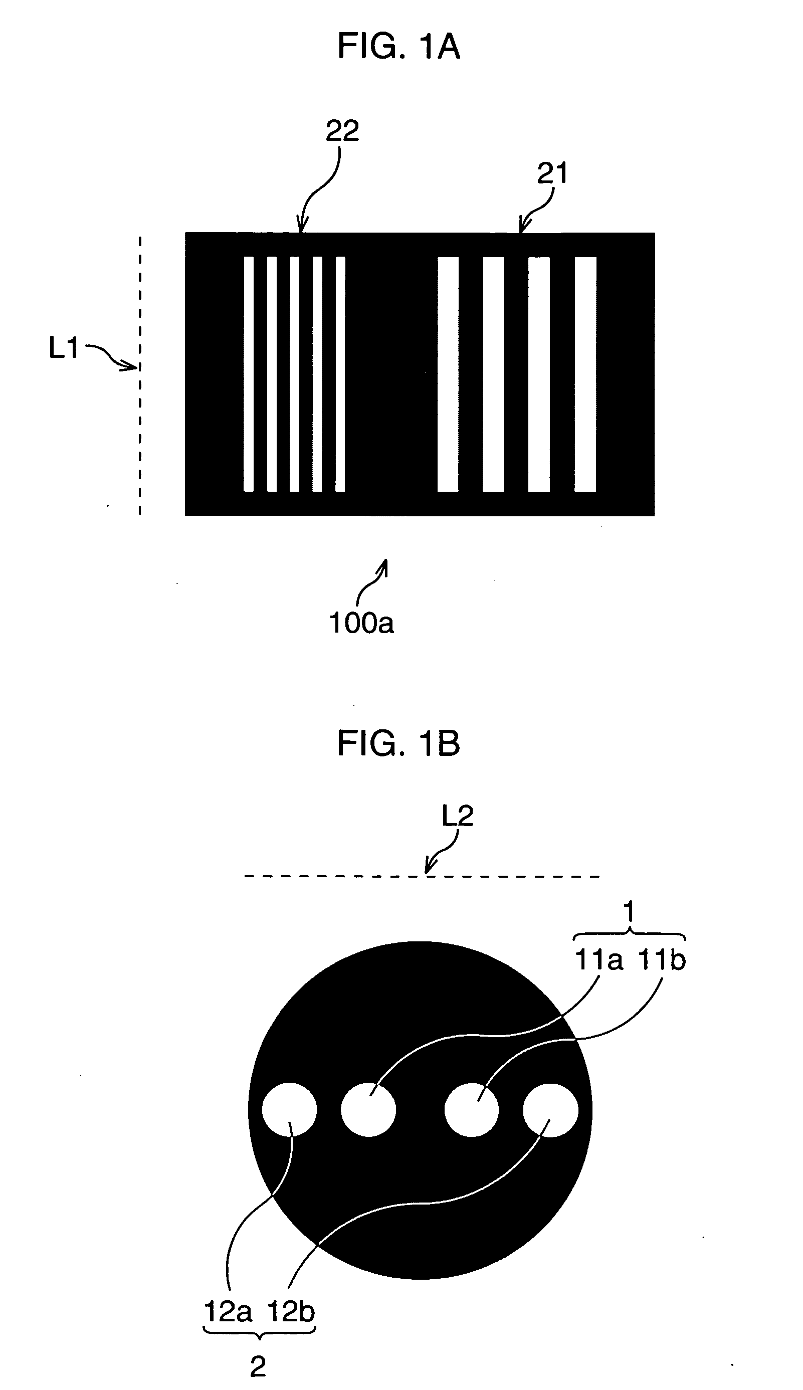
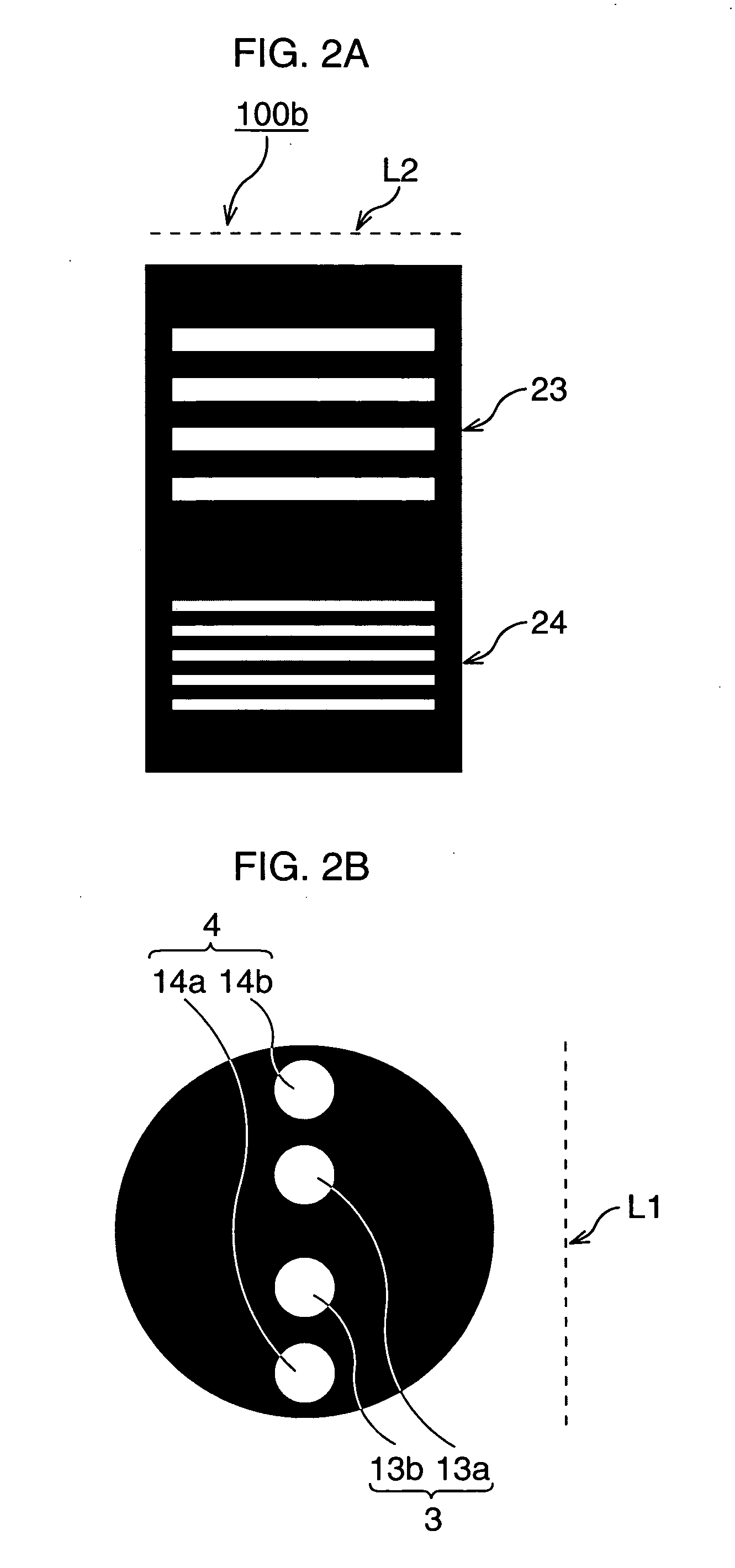
[0042]First, in order to correspond to exposure for performing patterning in which micropatterns differing in pitch exist in close vicinity to one another, the case where the patterns of the most frequent appearance are a several kinds of band-shaped patterns differing in pitch and extending in one direction is taken. Here, the case of bringing about the illumination state in which a plurality of double pole illuminations are combined at different po...


PUM


Abstract

Exposure for performing patterning in which micropatterns differing in pitch exist in close vicinity to one another is handled, and micropatterns are formed with high accuracy with sufficient manufacture process margins without using a photomask complicated in manufacturing process at high manufacture cost like an alternating phase shift mask. A light intensity distribution of irradiation light constituted of double pole illuminations is formed to correspond to L&S patterns. The double pole illumination is constituted of a pair of illumination modes, and the double pole illumination is constituted of a pair of illumination modes.

Description

CROSS-REFERENCE TO RELATED APPLICATIONS[0001]This application is based upon and claims the benefit of priority from the prior Japanese Patent Application No. 2006-210106, filed on Aug. 1, 2006, the entire contents of which are incorporated herein by reference.BACKGROUND OF THE INVENTION[0002]1. Field of the Invention[0003]The present invention relates to an illumination optical system which illuminates an object of irradiation, an aligner and an exposure method including the illumination optical system, and used in lithography for manufacturing various kinds of devises such as semiconductor devices and liquid crystal display devices, and a designing method of a device.[0004]2. Description of the Related Art[0005]With high densification of semiconductor elements, microfabrication of patterns formed with lithography has been advanced. As a method for accurately forming micropatterns, a multiple exposure process using an alternating phase shift mask is proposed.[0006]The method of the ...

Claims


Application Information

Patent Timeline
IPC IPC(8): G03B27/54
CPCG03B27/54
Inventor YAMAMOTO, TOMOHIKO
Owner FUJITSU SEMICON LTD
Why Eureka
Try Eureka