Drier screw conveying device for biomass power generation

A screw conveying device, biomass power generation technology, applied in the direction of conveyor objects, transportation and packaging, packaging, etc., can solve the problems of easy filling of the shell, uneven distribution of feeding materials, and difficulty in dredging, so as to prevent material filling, Good practicability, the effect of solving the phenomenon of uneven feeding

Inactive Publication Date: 2014-04-16
ZHAOYANG PNEUAMTIC HYDRAULIC MECHANICAL EQUIP JIANGSU
View PDF0 Cites 2 Cited by
  • Summary
  • Abstract
  • Description
  • Claims
  • Application Information

AI Technical Summary

Problems solved by technology

[0002] At present, the dry material shed screw is used in biomass power generation equipment for feeding the belt. The existing biomass power generation dry mater

Method used


Image

  • Drier screw conveying device for biomass power generation
  • Drier screw conveying device for biomass power generation

Examples


Embodiment Construction

[0013] The present invention will be further described below in conjunction with the accompanying drawings.

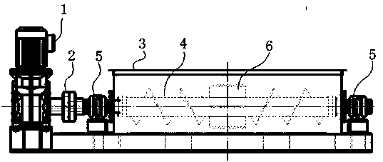
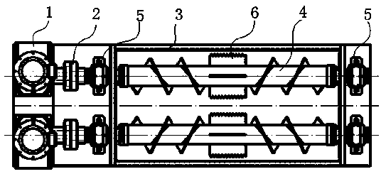
[0014] Such as figure 1 and figure 2 As shown, the feeding device for the biomass power generation silo includes a driving device 1, a coupling 2, a housing 3, a spiral body 4 and a bearing seat 5; the driving device 1 is connected to the coupling 2, and the coupling 2 is connected to the bearing Seat 5 links to each other, and bearing seat 5 links to each other with spiral body 4, and spiral body 4 can have two, is located in the shell 3 symmetrically and parallelly, all links to each other with bearing seat 5. The driving device 1 is a speed reducer, and is arranged on the side of the housing 1 . Preferably, the feeding device is arranged on the upper part of the tail belt of the belt conveyor.

[0015] When working, when the fuel is sent into the silo of the dry material shed through the transportation equipment, the material spiral will transfer the material fr...


PUM


Abstract

The invention discloses a drier screw conveying device for biomass power generation. The drier screw conveying device comprises a drive device, a coupler, a shell, a screw body and bearing pedestals. The screw body is arranged in the shell, and the bearing pedestals are connected to the two ends of the screw body; the coupler is connected with the bearing pedestals and driven by the drive device. The drier screw conveying device for biomass power generation has the advantages that the phenomenon of material fluffing in the feeding process can be effectively prevented through even rotation of shifting plates; rotation of the shifting plates enables the materials to be spread evenly, so the phenomenon of uneven material feeding is avoided; the drier screw conveying device for biomass power generation has good practicality and is capable of bringing excellent economic benefits and social effects.

Description

technical field [0001] The invention relates to biomass power generation equipment, in particular to a dry material screw conveying device for biomass power generation. Background technique [0002] At present, the dry material shed screw is used in biomass power generation equipment for feeding the belt. The existing biomass power generation dry material shed screw has the following disadvantages in the process of use: (1) It is easy to fill the shell and it is difficult to dredge . (2) The feed distribution is uneven. Therefore, it needs to be improved and innovated. Contents of the invention [0003] Purpose of the invention: In view of the deficiencies in the prior art, the purpose of the invention is to provide a dry material screw conveying device for biomass power generation, so that it has the characteristics of safety, reliability, stable operation, high conveying rate, economical and practical. [0004] Technical solution: In order to realize the above-mention...

Claims


Application Information

Patent Timeline
IPC IPC(8): B65G47/16B65G33/18B65G33/26
Inventor 陈翠萍翟慎会傅钧盖东飞袁健朱相国陆虎
Owner ZHAOYANG PNEUAMTIC HYDRAULIC MECHANICAL EQUIP JIANGSU
Why Eureka
Try Eureka