
Hot-wind solidification automatic cloth feeding (cloth leading) mechanism

An automatic and cloth-feeding technology, which is applied in the direction of winding strips, sending objects, thin material processing, etc., can solve problems such as difficult operation, affecting production efficiency, and product quality decline, and achieves improved working environment and labor intensity, and equipment Wide range of use and the effect of reducing working hours

Inactive Publication Date: 2014-04-16
DALIAN HUAYANG NEW MATERIALS TECH CO LTD
View PDF6 Cites 1 Cited by
  • Summary
  • Abstract
  • Description
  • Claims
  • Application Information

AI Technical Summary

Problems solved by technology

[0002] The existing hot air consolidation equipment mainly adopts two cloth feeding methods: side feeding and bottom feeding, neither of which has a separate automatic feeding method. Cloth (fabric introduction) device, if it is necessary to carry out hot air consolidation of the mesh cloth that has only been pre-hot rolled or pre-needled, it becomes a difficult problem to guide the cloth. Since the fiber mesh is soft and fluffy, when the hot air consolidation equipment is used In the bottom feeding method, the cloth feeding is difficult and requires manual operation, but the bottom feeding method results in a narrow operating space and is not easy to operate
In severe cases, it will cause the fiber mesh to accumulate on the conveyor belt or the mesh to be twisted and overlapped on the hot air wheel, resulting in a decline in product quality or products that cannot meet the standards, thereby affecting production efficiency

Method used


Image

  • Hot-wind solidification automatic cloth feeding (cloth leading) mechanism
  • Hot-wind solidification automatic cloth feeding (cloth leading) mechanism
  • Hot-wind solidification automatic cloth feeding (cloth leading) mechanism

Examples


specific Embodiment approach

[0014] Detailed ways Next, the present invention will be described in detail in conjunction with the accompanying drawings

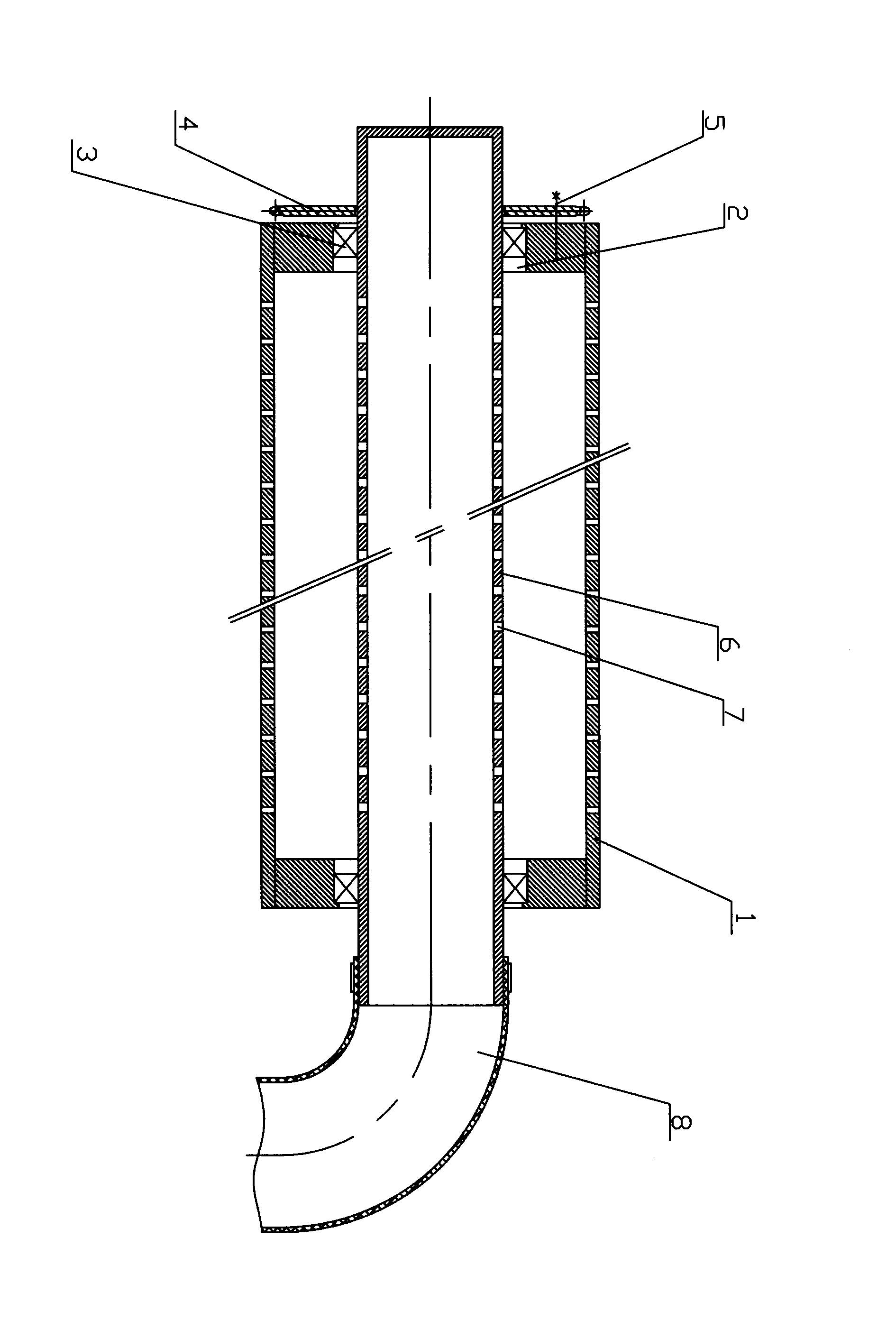
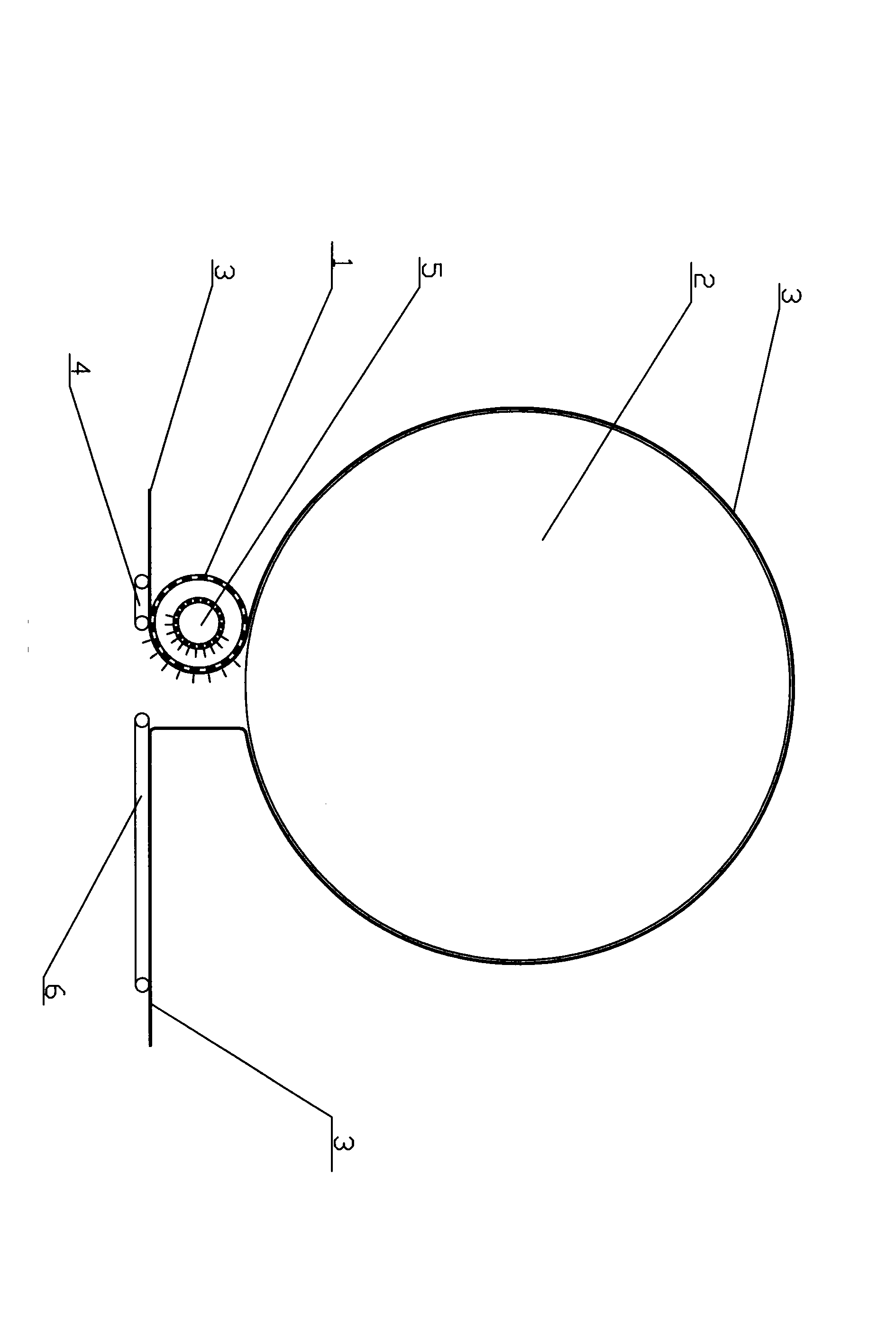
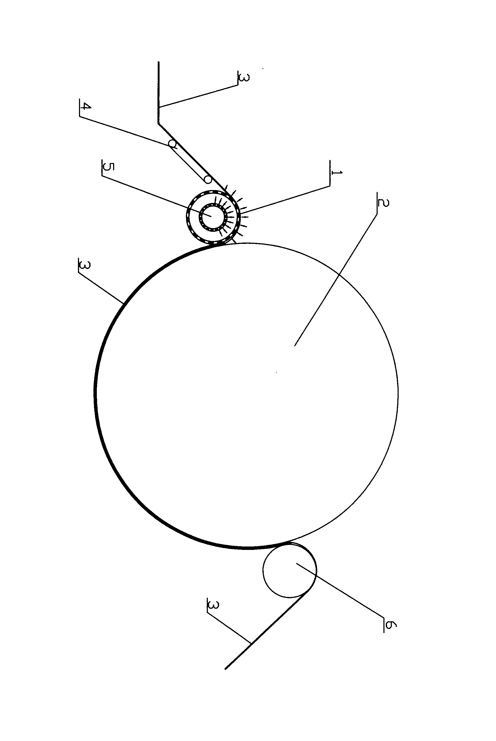
[0015] A hot air consolidation automatic cloth feeding (cloth leading) mechanism, such as figure 1 As shown, the horizontal outer roller 1 is a hollow round roller made of orifice plates, and the middle positions of the plates at both ends of the axial direction are respectively provided with coaxial through holes 2, and bearing seats 3 are respectively fixed in the through holes; the above outer rollers The axial side of the shaft is provided with a transmission gear 4 coaxial with it, and the transmission gear is connected with one side end plate of the outer roller through fastening bolts 5; 6. The inner roller is a hollow round roller with an opening at one end in the axial direction, and its outer peripheral wall is in contact with the bearing of the bearing seat. There are still several through holes on the inner roller, that is, the air suc...


PUM


Abstract

The invention discloses a hot-wind solidification automatic cloth feeding (cloth leading) mechanism. The middle portions of two axial end plates of a horizontal outer roller are provided with through holes coaxial with the horizontal outer roller respectively, and bearing bases are fixed inside the through holes respectively. The axial side of the outer roller is provided with a transmission gear coaxial with the outer roller. The transmission gear is connected with the end plate arranged on one side of the outer roller through a fastening bolt. Bearings of the two bearing bases are respectively and internally provided with a horizontal inner roller which is a hollow round roller with the axial end open, the outer circumferential walls of the inner rollers are connected with the bearings of the bearing bases, and the inner rollers are still provided with air suction holes. The non-open ends of the inner rollers penetrate through a center through hole in the transmission gear, and the open ends of the inner rollers are communicated with one end of a guide pipe. Compared with the prior art, the hot-wind solidification automatic cloth feeding (cloth leading) mechanism has the advantages that the cloth can be automatically led, and the cloth cannot be wrinkled or overlapped when entering a hot seal device through the automatic cloth leading device.

Description

technical field [0001] The invention belongs to the field of textile processing, and in particular relates to a cloth feeding or guiding mechanism of a non-woven cloth hot air consolidation device. Background technique [0002] The existing hot air consolidation equipment mainly adopts two cloth feeding methods: side feeding and bottom feeding. Neither of the two feeding methods has a separate automatic cloth feeding (cloth feeding) device. If necessary, it will only be pre-heated. Or when the pre-needled mesh is subjected to hot air consolidation, the cloth introduction becomes a problem. Since the fiber mesh is soft and fluffy, when the hot air consolidation equipment adopts the cloth feeding method from the bottom, it is difficult to feed the cloth and requires manual operation, but The cloth feeding method from the bottom causes the operation space to be narrow and not easy to operate. In severe cases, it will cause the fiber mesh to accumulate on the conveyor belt or ...

Claims


Application Information

Patent Timeline
IPC IPC(8): B65H20/12B65H37/00
Inventor 关跃跃高娜刘希君孙德明
Owner DALIAN HUAYANG NEW MATERIALS TECH CO LTD
Learn More