Stirring mechanism of asphalt stone mixing and stirring heating tank

A technology of mixing and stirring mechanism, applied in the direction of roads, road repair, roads, etc., can solve the problems of poor mixing effect, low efficiency, single mixing function, etc., and achieve the effect of convenient implementation, uniform mixing and reasonable design

Inactive Publication Date: 2016-02-24
GUANGDONG ESUN HEAVY IND CO LTD
View PDF5 Cites 0 Cited by
  • Summary
  • Abstract
  • Description
  • Claims
  • Application Information

AI Technical Summary

Problems solved by technology

[0003] In the prior art, the mixer generally includes a mixing mechanism and a mixing chamber for accommodating hot asphalt and dried heated crushed stones. The mixing mechanism includes a stirring shaft extending into the mixing chamber and a number of stirring blades installed on the stirring shaft. Generally, several stirring blades are arranged on the same circumference and form a group. Several groups of such blades are arranged at intervals along the axis of the stirring shaft. This arrangement of the stirring blades, on the one hand, has poor stirring uniformity and poor stirring effect. And the efficiency is low; on the other hand, the mixing mechanism only has a single mixing function, and cannot realize the cutting, crushing and conveying functions of the mixed material after mixing asphalt and stone. If the mixed material is to be transported, an additional screw feeding mechanism must be configured

Method used


Image

  • Stirring mechanism of asphalt stone mixing and stirring heating tank
  • Stirring mechanism of asphalt stone mixing and stirring heating tank
  • Stirring mechanism of asphalt stone mixing and stirring heating tank

Examples


Embodiment Construction

[0035] The present invention will be further described in detail below in conjunction with the accompanying drawings and specific embodiments.

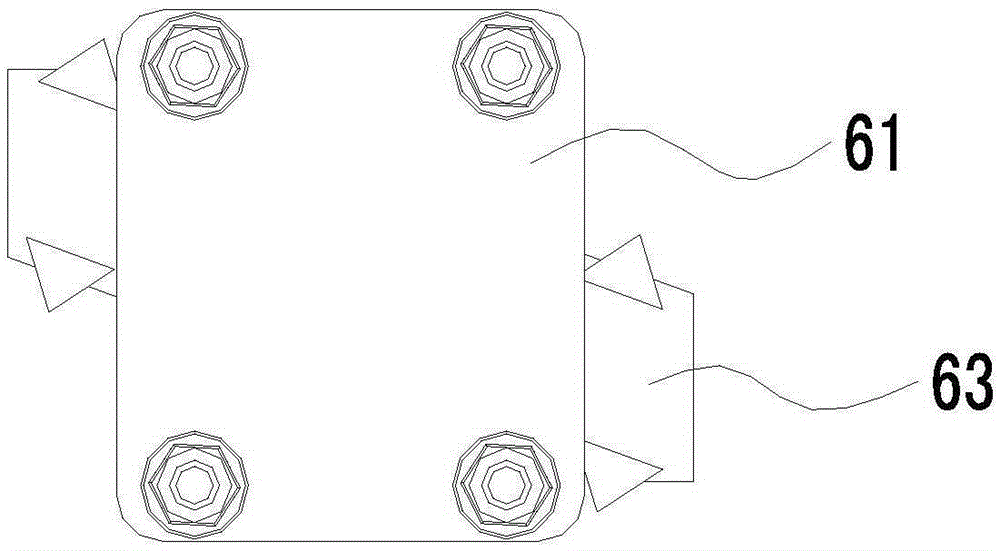
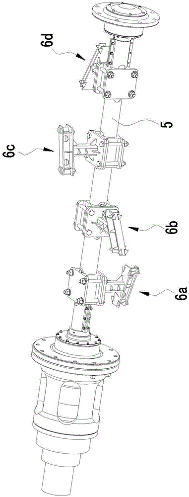
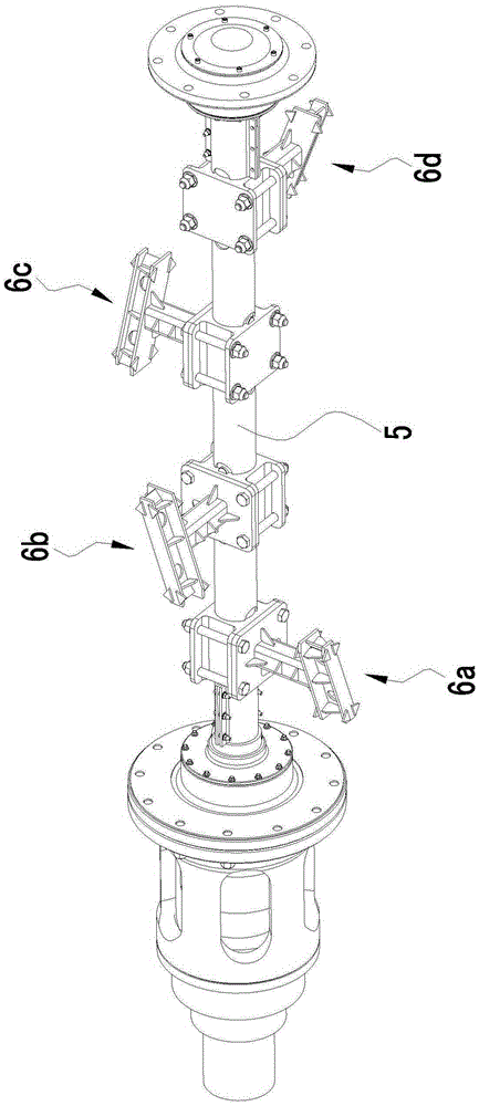
[0036] like Figure 1 to Figure 12 As shown, a stirring mechanism of an asphalt stone mixing and stirring heating tank includes a stirring shaft 5 and a plurality of stirring blades 6 installed on the stirring shaft. 5 are arranged at intervals in the axial direction, each stirring blade 6 includes a base 61, a stirring arm 62 and a blade portion 63, one end of the stirring arm 62 is connected to the base 61, the other end of the stirring arm 62 is connected to the blade portion 63, and the base 61 is installed on On the stirring shaft 5, the projections of two adjacent stirring blades 6 on a plane perpendicular to the axis M of the stirring shaft form a "V" shape, and the blade parts 63 of all the stirring blades are spatially arranged in a helical shape. The stirring shaft 5 can be driven by the power mechanism of the stirring heat...


PUM


Abstract

The invention relates to a stirring mechanism for mixing, stirring and heating kettle of bituminous materials and aggregates. The stirring mechanism includes a stirring shaft and a plurality of stirring blades mounted on the stirring shaft, wherein the rotary stirring shaft drives the stirring blades to rotate; the stirring blades are arrayed at intervals in the axial direction of the stirring shaft; each stirring blade includes a base, a stirring arm and a blade part; one end of the stirring arm is connected with the base, the other end of the stirring arm is connected with the blade part, and the base is mounted on the stirring shaft; the projection of the two adjacent stirring blades on the plane vertical to the axis of the stirring shaft is V-shaped; the blade parts of all the stirring blades are arrayed to be spiral in space. The stirring mechanism is uniform in stirring operation and better in stirring effect and improves the stirring efficiency, through the arrangement manner of all the blade parts, the mixture of mixed bituminous materials and aggregates can be conveyed during the rotation of the blade parts, so as to give assistance to discharge, as a result, the stirring mechanism can be used for conveying the mixture, and when the mixture is stirred, the stirring blades can be used for pushing and squeezing the mixture, and all the stirring blades can be used for cutting and smashing the mixture.

Description

technical field [0001] The invention relates to a stirring mechanism of an asphalt stone material mixing and stirring heating kettle. Background technique [0002] Asphalt concrete is artificially selected with a certain grade of mineral materials (crushed stone or crushed gravel, stone chips or sand, mineral powder, etc.) and a certain proportion of road asphalt materials, and mixed under strictly controlled conditions. of the mixture. The traditional preparation process of asphalt concrete generally first heats and melts the asphalt glue and dries and heats the crushed stone, and then puts the hot asphalt and the dried and heated crushed stone into the mixer for mixing. [0003] In the prior art, the mixer generally includes a mixing mechanism and a mixing chamber for accommodating hot asphalt and dried heated crushed stones. The mixing mechanism includes a stirring shaft extending into the mixing chamber and a number of stirring blades installed on the stirring shaft. G...

Claims


Application Information

Patent Timeline
Patent Type & Authority Patents(China)
IPC IPC(8): E01C19/10
Inventor 贾永力邹慧娟杨刚黄开金薛浩帅李熙吴土祥
Owner GUANGDONG ESUN HEAVY IND CO LTD
Why Eureka
Try Eureka