Negative step force testing system
A negative step force, test system technology, applied in the direction of force/torque/work measuring instrument calibration/testing, force/torque/work measuring instrument, measuring device, etc. The problem is not large, the static load is limited, etc., to achieve the effect of adjustable falling edge time, large initial force, and short falling edge time
- Summary
- Abstract
- Description
- Claims
- Application Information
AI Technical Summary
Problems solved by technology
Method used
Image
Examples
Embodiment 1
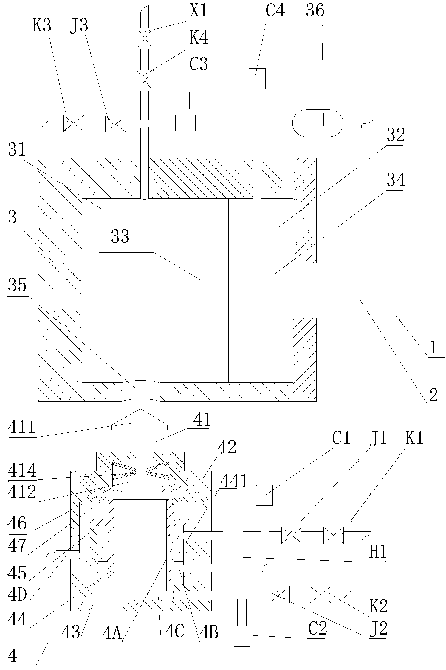
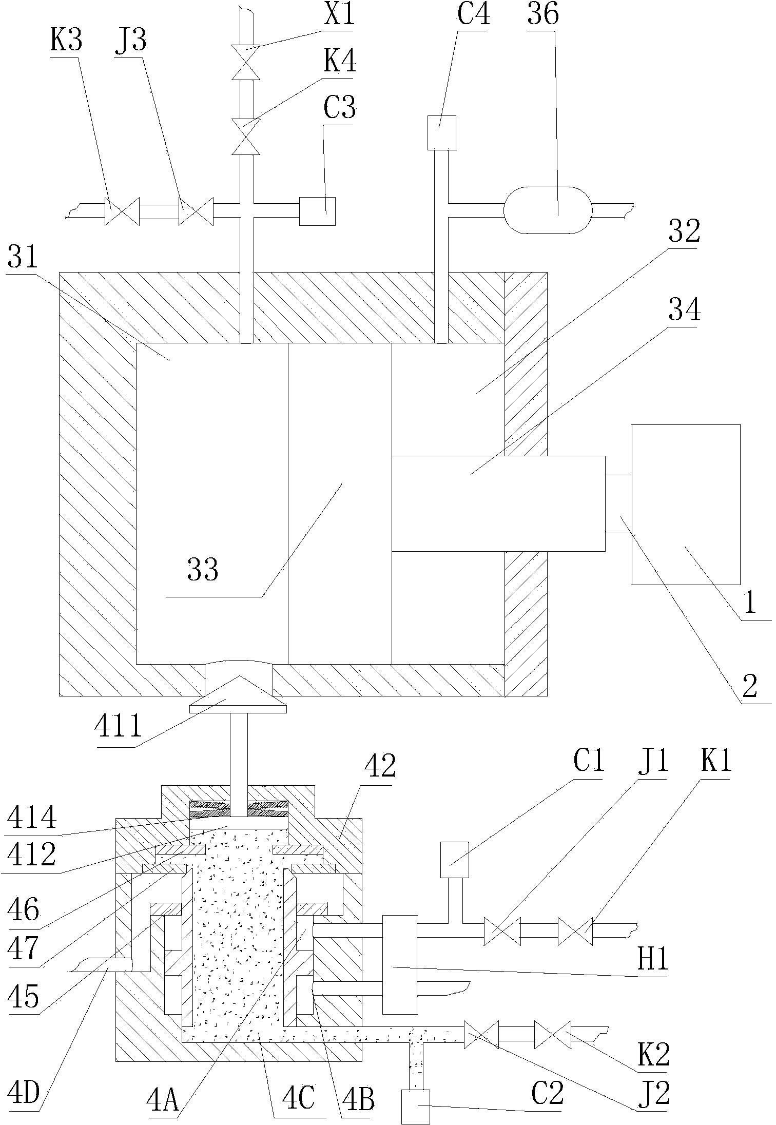
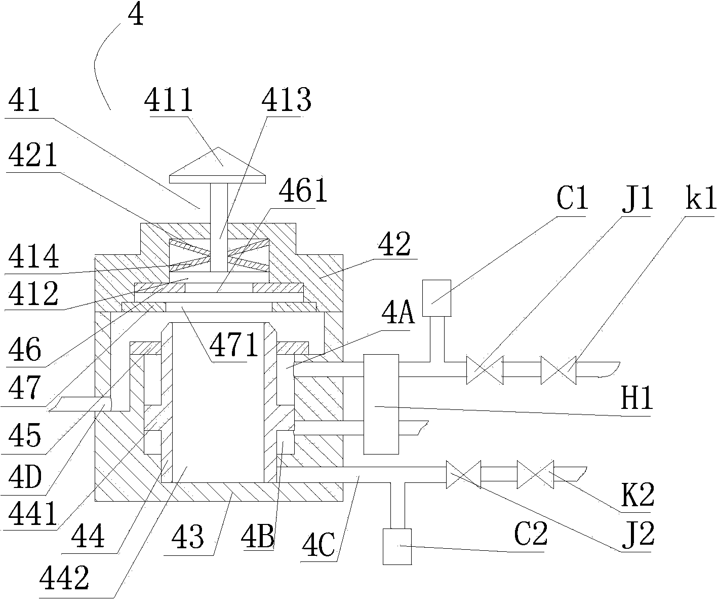
[0034] refer to Figure 1-3
[0035] The negative step force test system includes the device under test 1, the force sensor 2 fixed on the device under test 1 and the negative step force generating device that applies force to the device under test 1; the negative step force generating device includes a pressure cylinder 3. The pressure control circuit connected to the pressure cylinder 3, the pressure piston 33 that separates the inner chamber of the pressure cylinder into the first pressure chamber 31 and the second pressure chamber 32, the piston rod 34 fixedly connected with the pressure piston 33, and the pressure piston 34 that is set at the pressure The unloading port 35 on the cylinder 3, and the unloading valve 4 that is adapted to the unloading port 35 and can quickly open the unloading port 35;
[0036] The unloading port 35 is set in the first pressure chamber 31, the piston rod 34 passes through the second pressure chamber 32, the exposed end of the piston rod 34...
Embodiment 2
[0053] refer to Figure 4
[0054] The difference between this embodiment and the first embodiment is that an unloading valve seat 48 is added between the pressure cylinder 3 and the valve body mounting seat 42 of the unloading valve 4 to limit the flow of the working medium of the pressure cylinder 3 . All the other structures are the same as the first embodiment.
[0055] Specifically, the unloading valve 4 also includes an unloading valve seat 48, the unloading valve seat 48 is arranged between the pressure cylinder 3 and the valve body mounting seat 42, the unloading valve seat 48 is hollow and fixedly connected with the pressure cylinder 3, The unloading valve seat 48 , the valve body mounting seat 42 and the pressure cylinder 3 form an unloading chamber 4E, and the unloading chamber 4E has a pressure discharge port 481 communicating with the outside. When the pressure cylinder 3 is a pneumatic cylinder, a second muffler X2 is arranged on the pressure discharge port.
...
Embodiment 3
[0058] refer to Figure 5
[0059] The difference between the present embodiment and the second embodiment is that the first pressure chamber 31 is provided with a boss 311 extending toward the direction of the pressure piston 33, and there is a gap between the boss 311 and the pressure cylinder 3, and the gap communicates with the pressure control circuit And pressure relief port 35. All the other structures are the same as the second embodiment.
[0060] The technical idea of this embodiment is to reduce the volume of the first pressure chamber 31 by setting a boss. The smaller the volume of the first pressure chamber 31 is, the shorter the required unloading time is. The shorter the unloading time, the faster the pressure in the first pressure chamber 31 drops, and the faster the output thrust of the pressure piston 33 drops; at the same time, the pressure piston 33 moves rapidly to the left under the pressure in the second pressure chamber 32, which is consistent with...
PUM
 Abstract
Description
Claims
Application Information
 - R&D
- Intellectual Property
- Life Sciences
- Materials
- Tech Scout
- Unparalleled Data Quality
- Higher Quality Content
- 60% Fewer Hallucinations
Browse by: Latest US Patents, China's latest patents, Technical Efficacy Thesaurus, Application Domain, Technology Topic, Popular Technical Reports.
© 2025 PatSnap. All rights reserved.Legal|Privacy policy|Modern Slavery Act Transparency Statement|Sitemap|About US| Contact US: help@patsnap.com


