
LED display screen, full-color LED light-emitting panel and manufacturing method of full-color LED light-emitting panel

A technology of light-emitting panels and LED lights, which is applied in the direction of instruments, identification devices, etc., and can solve problems such as high processing temperature requirements, difficult maintenance of full-color LED light-emitting panels, and virtual soldering.

Inactive Publication Date: 2014-04-16
SHENZHEN AUROLED TECH
View PDF6 Cites 5 Cited by
  • Summary
  • Abstract
  • Description
  • Claims
  • Application Information

AI Technical Summary

Problems solved by technology

This leads to some defects in the existing full-color LED light-emitting panels: the packaging process of the LED lamp is complicated and the cost is high; since the LED lamp and the PCB circuit board are connected by solder paste welding, the heat dissipation of the LED lamp can only be through the PCB circuit board The solder pad dissipates heat, and the heat dissipation capacity is limited; in addition, due to the use of solder paste materials in the processing process, the processing temperature requirements are very high, which makes the products easy to age and solder in the later stage, and the service life is short; Smaller, full-color LED-lit panels are more difficult to maintain
These defects lead to the application of full-color LED light-emitting panels to indoor full-color display screens with small spacing, which has great limitations.

Method used


Image

  • LED display screen, full-color LED light-emitting panel and manufacturing method of full-color LED light-emitting panel
  • LED display screen, full-color LED light-emitting panel and manufacturing method of full-color LED light-emitting panel
  • LED display screen, full-color LED light-emitting panel and manufacturing method of full-color LED light-emitting panel

Examples


Embodiment Construction

[0032] Now in conjunction with the accompanying drawings, the preferred embodiments of the present invention will be described in detail.

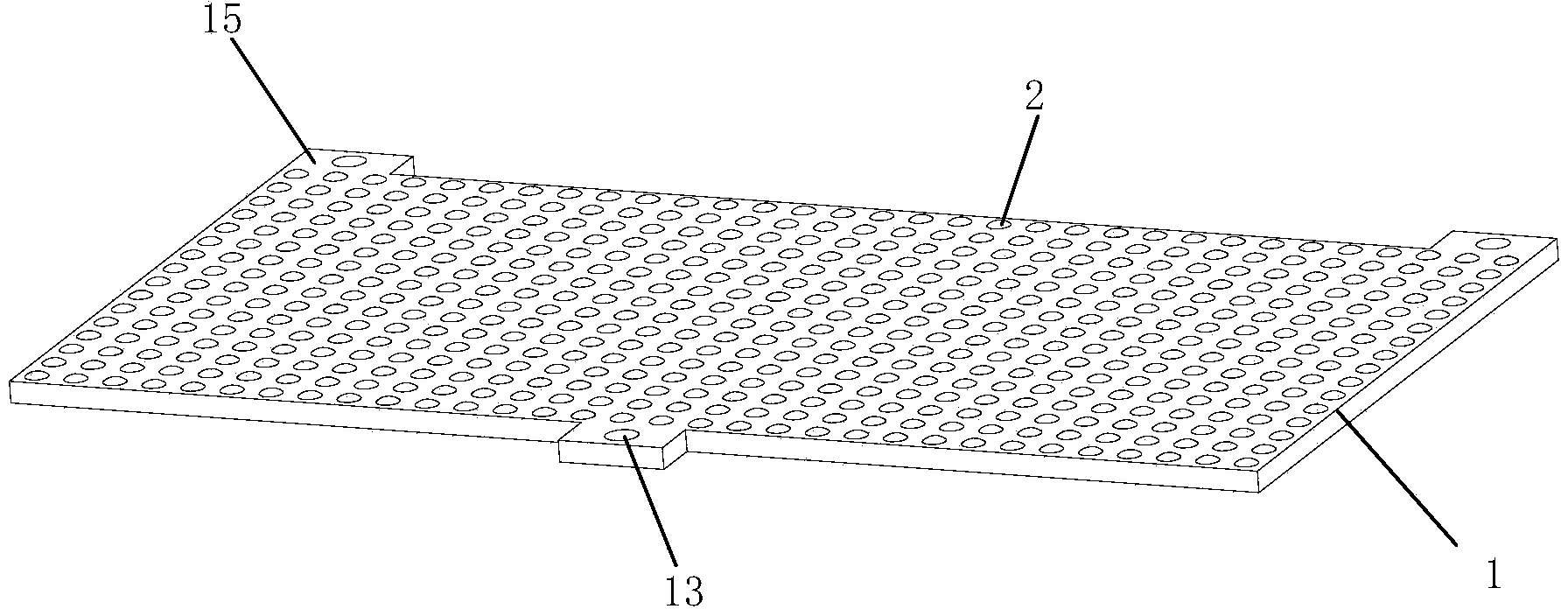
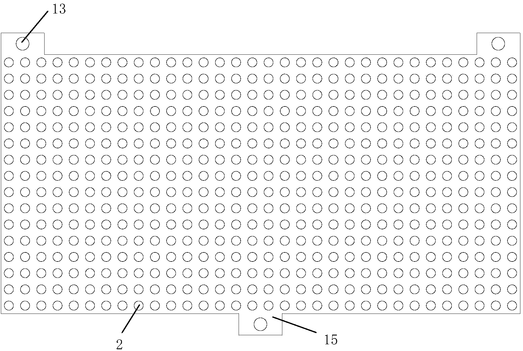
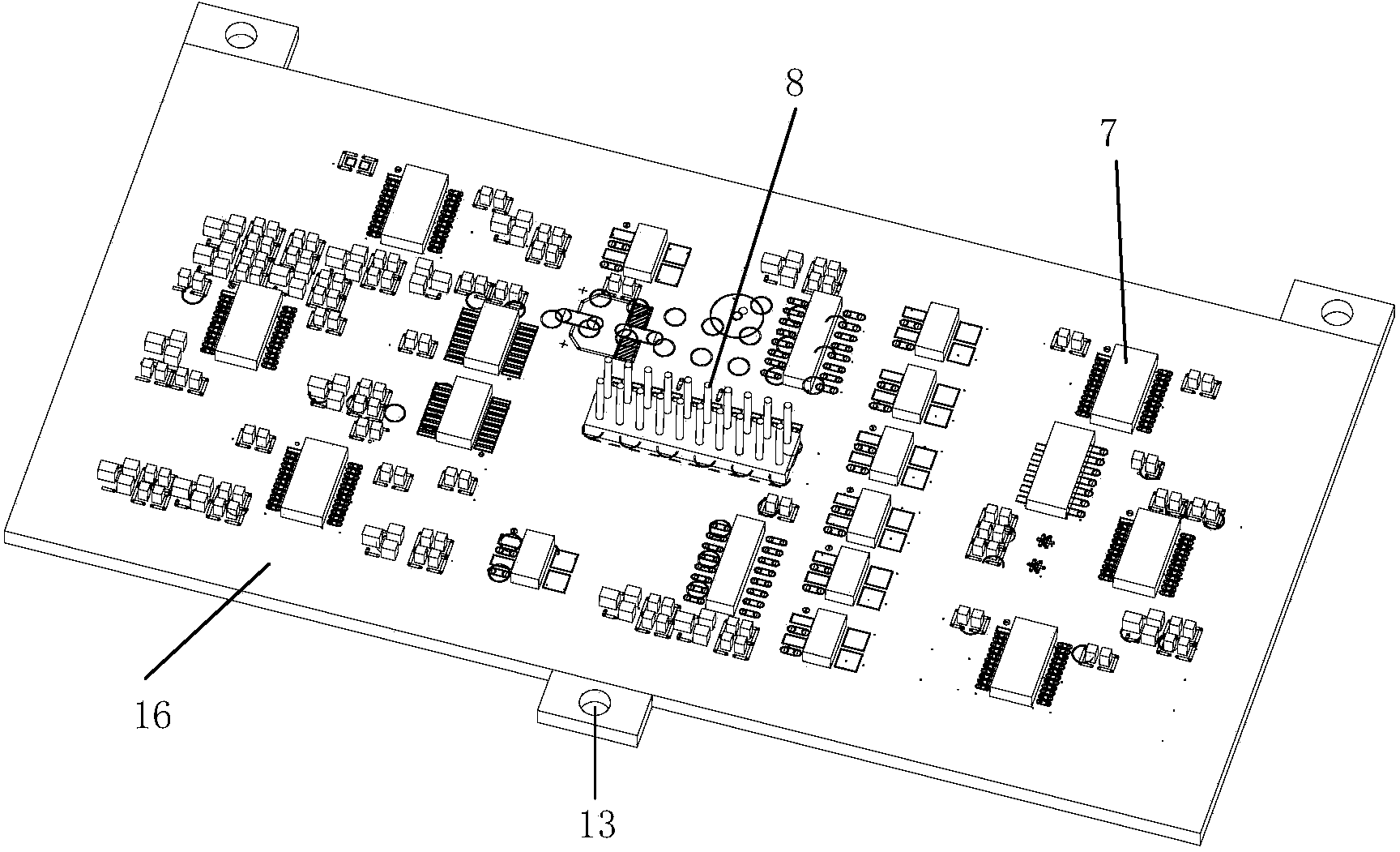
[0033] The invention provides an LED display screen, which has a full-color LED light-emitting panel. The full-color LED light-emitting panel includes a circuit board, an LED lamp array and a driving circuit arranged on the circuit board, and the circuit board is a printed circuit board, preferably a black core printed circuit board, which can also be Choose another PCB. The circuit board includes an opposite first surface and a second surface, the LED lamp array is arranged on the first surface of the circuit board, and the driving circuit is installed on the second surface of the circuit board; wherein, the An array of concave holes is formed on the first surface, and a plurality of immersion gold pads are provided at the bottom of each concave hole; the LED array is a full-color LED lamp array, and each full-color LED lamp is correspon...


PUM


Abstract

The invention discloses an LED display screen, a full-color LED light-emitting panel and a manufacturing method of the full-color LED light-emitting panel. The LED display screen comprises a circuit board, an LED lamp array arranged on the circuit board, and a drive circuit arranged on the circuit board. The circuit board comprises a first face and a second face, wherein the first face and the second face are opposite. The LED lamp array is arranged on the first face of the circuit board, and the drive circuit is arranged on the second face of the circuit board. A concave hole array is formed in the first face, and a plurality of immersion gold welding plates are arranged at the bottom of each concave hole. The LED lamp array is a full-color LED lamp array, and each full-color LED lamp is packaged in the corresponding concave hole. Each full-color LED lamp comprises LED light-emitting wafers which are in three colors and are fixed to the corresponding immersion gold welding plates in a binding mode, and lenses which are formed on the corresponding LED light-emitting wafers in three colors in an epoxy potted mode and a covering mode to seal the corresponding concave holes. The LED display screen and the full-color LED light-emitting panel can be widely applied to indoor full-color display in a small distance.

Description

technical field [0001] The invention relates to a display device, in particular to an LED display screen. Background technique [0002] The full-color LED light-emitting panel is the main component of the LED display. Existing full-color LED light-emitting panels are usually composed of components such as LED lights, PCB circuit boards, integrated circuits, resistors, capacitors, MOS tubes, electrical connection sockets, and plastic kits. The packaging method of the existing LED lamp is generally as follows: first use the crystal bonder to bind the LED chip on the LED lamp bracket, after high-temperature baking, then use the wire bonding machine to wire-bond the LED chip, and then go through high-temperature baking again. Finally, use the test equipment to test, use the repair equipment to repair the defective products, use the dispensing machine to dispens the bound LED lamp cups for the qualified products, and then bake at high temperature, and then use The cutting equip...

Claims


Application Information

Patent Timeline
IPC IPC(8): G09F9/33
Inventor 陈小勇蒋顺才
Owner SHENZHEN AUROLED TECH
Learn More