Supercharge Your Innovation With Domain-Expert AI Agents!

Electronic module

An electronic module and winding frame technology, which is applied to circuits, electrical components, antenna supports/installation devices, etc., can solve the problem that more precise adjustment cannot be obtained, the resonant frequency of the floating capacitor cannot be obtained, and the floating of the coil cannot be adjusted. Capacitance and other problems, to achieve the effect of good winding state and prevent deviation

Active Publication Date: 2014-04-16
SUMIDA CORP
View PDF1 Cites 2 Cited by
  • Summary
  • Abstract
  • Description
  • Claims
  • Application Information

AI Technical Summary

Problems solved by technology

[0003] The existing small antenna coil products are usually unable to adjust the floating capacitance of the coil. The state of the winding determines the state of the floating capacitance. In this way, the corresponding resonant frequency cannot be adjusted effectively because the floating capacitance cannot be adjusted effectively. precise adjustment

Method used


Image

  • Electronic module
  • Electronic module
  • Electronic module

Examples


Embodiment 1

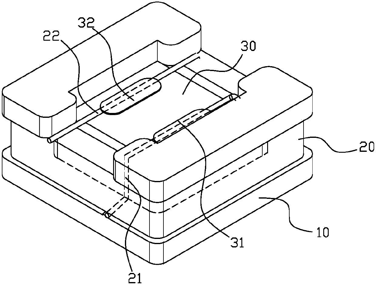
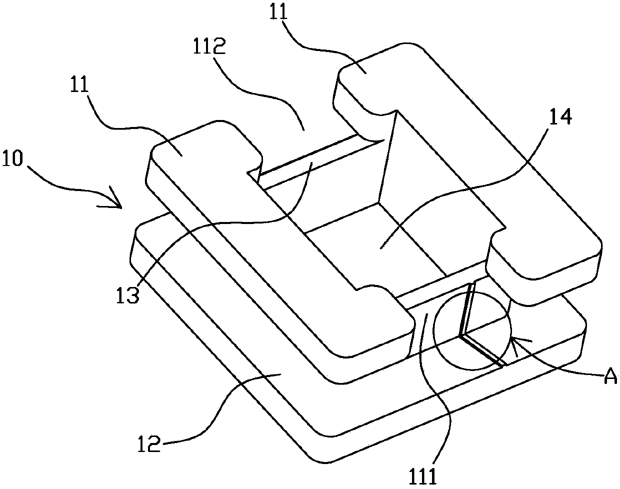
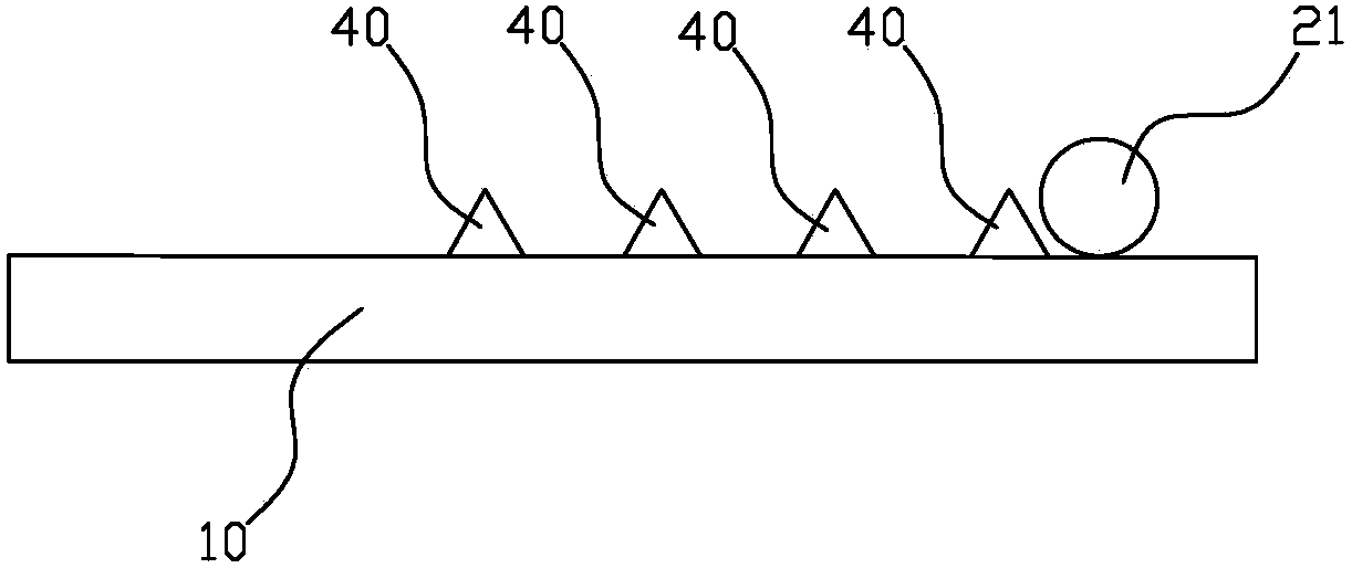
[0029] Such as Figure 1 to Figure 3 As shown, an electronic module includes a winding frame 10, a chip 30, and a coil 20. The winding frame 10 is provided with a receiving slot 14, the chip 30 is installed in the receiving slot 14, and the coil 20 is wound around the winding frame. On the bobbin 10, the coil 20 has a start part 21 and an end part 22. The start part 21 and the end part 22 are respectively electrically connected to the chip 30. The outer wall of the bobbin 10 is provided with four A positioning mechanism for positioning the starting portion 21.

[0030] Wherein, the positioning mechanism is a strip-shaped protrusion 40. The winding frame 10 includes a winding part 13 and a supporting wall plate, the winding part 13 is fixedly arranged on the supporting wall plate, and the winding part 13 and the supporting wall plate enclose the containing groove 14 The strip-shaped protrusion 40 is provided on the outer wall of the winding part 13, and the coil 20 is wound on t...

Embodiment 2

[0041] Such as figure 1 , figure 2 with Figure 4 As shown, an electronic module includes a winding frame 10, a chip 30, and a coil 20. The winding frame 10 is provided with a receiving slot 14, the chip 30 is installed in the receiving slot 14, and the coil 20 is wound around the winding frame. On the bobbin 10, the coil 20 has a start part 21 and an end part 22. The start part 21 and the end part 22 are electrically connected to the chip 30, respectively. The outer wall of the bobbin 10 is provided with four A positioning mechanism for positioning the starting portion 21.

[0042] Wherein, the positioning mechanism is a strip-shaped recess 50. The winding frame 10 includes a winding part 13 and a supporting wall plate, the winding part 13 is fixedly arranged on the supporting wall plate, and the winding part 13 and the supporting wall plate enclose the containing groove 14 The strip-shaped recess 50 is provided on the outer wall of the winding portion 13, and the coil 20 is w...


PUM


Abstract

The invention discloses an electronic module which comprises a reel, a chip and a coil. The reel is provided with an accommodation groove, the chip is arranged in the accommodation groove, the coil is wound on the reel and comprises a head portion and a tail portion, and the head portion and the tail portion are electrically connected with the chip respectively. At least one locating mechanism used for locating the head portion is arranged on the outer wall of the reel. The electronic module determines the position of the head portion of the coil through the locating mechanism, the winding state of the coil is changed by adjusting the position of the head portion of the coil on the corresponding locating mechanism, and accurate adjustment of coil resonant frequency is achieved.

Description

Technical field [0001] The invention relates to an electronic module, in particular to an NFC electronic module. Background technique [0002] Generally, the data exchange system of wireless communication realizes data exchange by setting the resonant frequency of the antennas suitable for the communicating parties. Among them, an example of using antennas to exchange data is an antenna coil for NFC. Generally, antenna coils used for NFC are mostly encapsulated in products such as cards. At this time, the resonant frequency set at the beginning may deviate from the resonant frequency due to packaging molding and cannot work normally. In addition, the frequency used for data exchange in NFC technology is sometimes not just a single frequency. When multiple frequencies are used for data exchange, the frequency bandwidth of the antenna coil used will be increased as much as possible. The specific method is to adjust the floating capacitance of the antenna coil (such as the capacit...

Claims


Application Information

Patent Timeline
Patent Type & Authority Applications(China)
IPC IPC(8): H01Q7/00H01Q1/14
CPCH04B5/72H04B5/24
Inventor 上田穗积万军
Owner SUMIDA CORP
Features
  • R&D
  • Intellectual Property
  • Life Sciences
  • Materials
  • Tech Scout
  • Unparalleled Data Quality
  • Higher Quality Content
  • 60% Fewer Hallucinations
Learn More