Device for testing communication error rate and sensitivity of light module

A test device and bit error rate technology, which is applied in the field of optical communication, can solve problems affecting test accuracy and test efficiency, complex functions, and expensive prices, so as to facilitate mass production test control, improve product quality and performance, and reduce effect of demand

Active Publication Date: 2014-04-16
WUHAN TELECOMM DEVICES
View PDF4 Cites 28 Cited by
  • Summary
  • Abstract
  • Description
  • Claims
  • Application Information

AI Technical Summary

Problems solved by technology

The multi-channel optical module needs to test the photoelectric indicators of each channel at the same time. In order to perform multi-channel testing at the same time, it is necessary to use multiple sets of single-channel test equipment or multi-channel equipment and optical power meters, attenuators, and oscilloscopes to achieve testing. Well-known instrument manufacturers The functions of single-channel and multi-channel test equipment are complicated and expensive. The tests of multi-channel optical modules mainly include bit error rate, sensitivity, eye diagram, etc. Among them, the cost of bit error meter and oscilloscope is relatively high, but they need to be used many times in production testing
When testing the sensitivity of an optical module, it is necessary to use an optical attenuator to adjust the input optical power to find the minimum input optical power that meets the test bit error rate requirements. These test processes require frequent insertion and removal of optical fibers to test the optical power in this case size, multiple plugging and unplugging of optical fibers will affect test accuracy and test efficiency

Method used


Image

  • Device for testing communication error rate and sensitivity of light module
  • Device for testing communication error rate and sensitivity of light module
  • Device for testing communication error rate and sensitivity of light module

Examples


Embodiment Construction

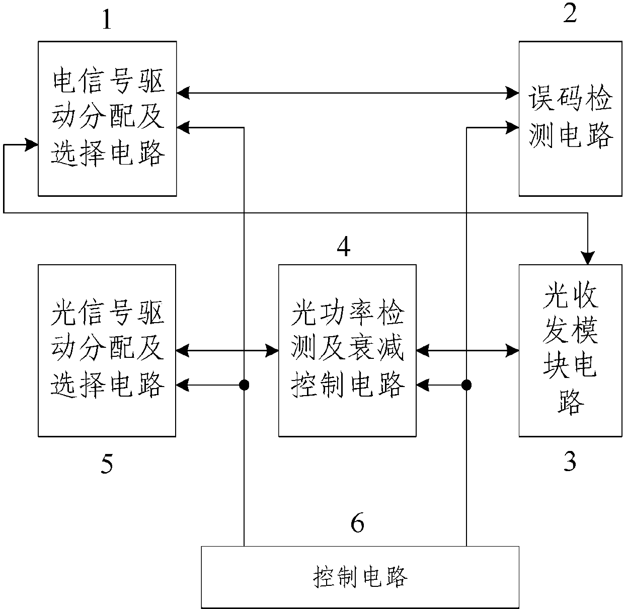
[0059] Such as figure 1 As shown, the test device for optical module communication bit error rate and sensitivity of the present invention is an electrical signal drive distribution and selection circuit 1, an error detection circuit 2, an optical transceiver module circuit 3, an optical power detection and attenuation control circuit 4, and an optical signal drive distribution And selection circuit 5 and control circuit 6.

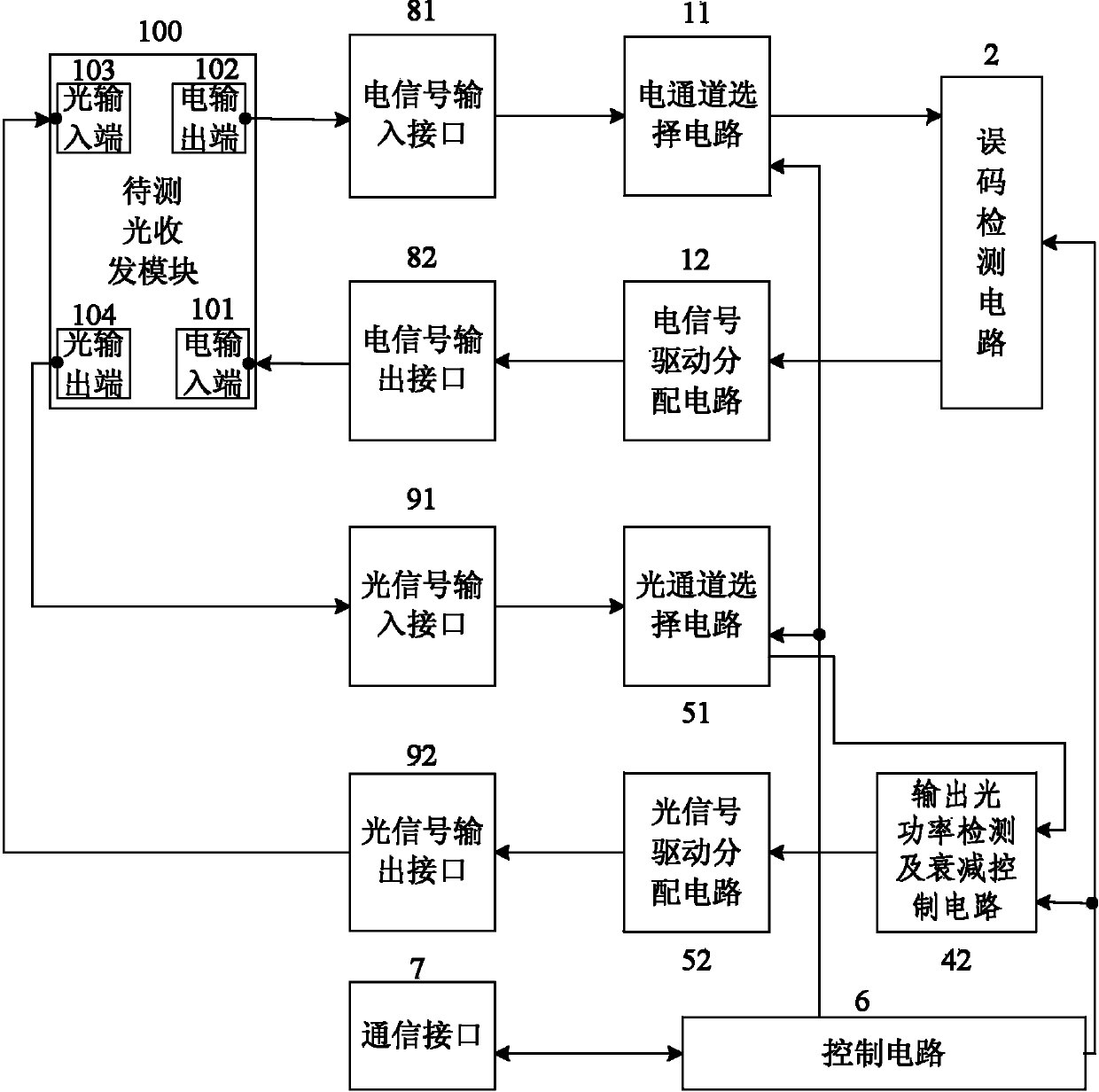
[0060]Wherein, the electrical signal driving distribution and selection circuit 1 can divide one channel into multiple channels, and can select the channel to output an electrical signal, and the electrical signal driving distribution and selection circuit 1 is connected to the optical transceiver module 100 to be tested (such as image 3 shown).

[0061] The code error detection circuit 2 can generate and output a code error electrical signal, and can also receive and detect a code error electrical signal. The code error detection circuit 2 is connected...


PUM


Abstract

The invention discloses a device for testing the communication error rate and the sensitivity of a light module. The device is connected with a light receiving and emitting module to be tested and comprises an electric signal driving distribution and selection circuit, an error rate detection circuit, a light receiving and emitting module circuit, a light power detection and attenuation control circuit, a light signal driving distribution and selection circuit and a control circuit. The control circuit respectively controls a channel of electric signals output by the electric signal driving distribution and selection circuit, a channel of light signals output by the light signal driving distribution and selection circuit, the attenuation amount of light signals of the light power detection and attenuation control circuit and the detection error rate and the sensitivity of the error rate detection circuit. According to the device for testing the communication error rate and the sensitivity of the light module, signals transmitted simultaneously by different channels of the multi-channel light module can be tested, the problems that optical fibers need to be plugged and pulled multiple times in the error rate testing process, the sensitivity testing process and the light emitting power testing process of the light module so that the light power can be tested can be avoided, and the test efficiency and the reliability of test results are improved.

Description

technical field [0001] The invention relates to the field of optical communication, in particular to a test device for the bit error rate and sensitivity of optical module communication. Background technique [0002] With the improvement of transmission rate and capacity requirements of optical modules in communication systems, large-capacity and high-speed optical modules have been developed rapidly. , has been widely used. The multi-channel optical module needs to test the photoelectric indicators of each channel at the same time. In order to perform multi-channel testing at the same time, it is necessary to use multiple sets of single-channel test equipment or multi-channel equipment and optical power meters, attenuators, and oscilloscopes to achieve testing. Well-known instrument manufacturers The functions of single-channel and multi-channel test equipment are complicated and expensive. The tests of multi-channel optical modules mainly include bit error rate, sensitivi...

Claims


Application Information

Patent Timeline
Patent Type & Authority Applications(China)
IPC IPC(8): H04B10/07
Inventor 林楠柏柳
Owner WUHAN TELECOMM DEVICES
Why Eureka
Try Eureka