
Endoillumination using decentered fiber launch

一种光纤、照明器的技术,应用在显微外科探头领域,能够解决难以制造小规格的内照明器等问题

Inactive Publication Date: 2014-04-16
ALCON RES LTD
View PDF9 Cites 1 Cited by
  • Summary
  • Abstract
  • Description
  • Claims
  • Application Information

AI Technical Summary

Problems solved by technology

These two considerations make it difficult to manufacture small format inner illuminators

Method used


Image

  • Endoillumination using decentered fiber launch
  • Endoillumination using decentered fiber launch
  • Endoillumination using decentered fiber launch

Examples


Embodiment Construction

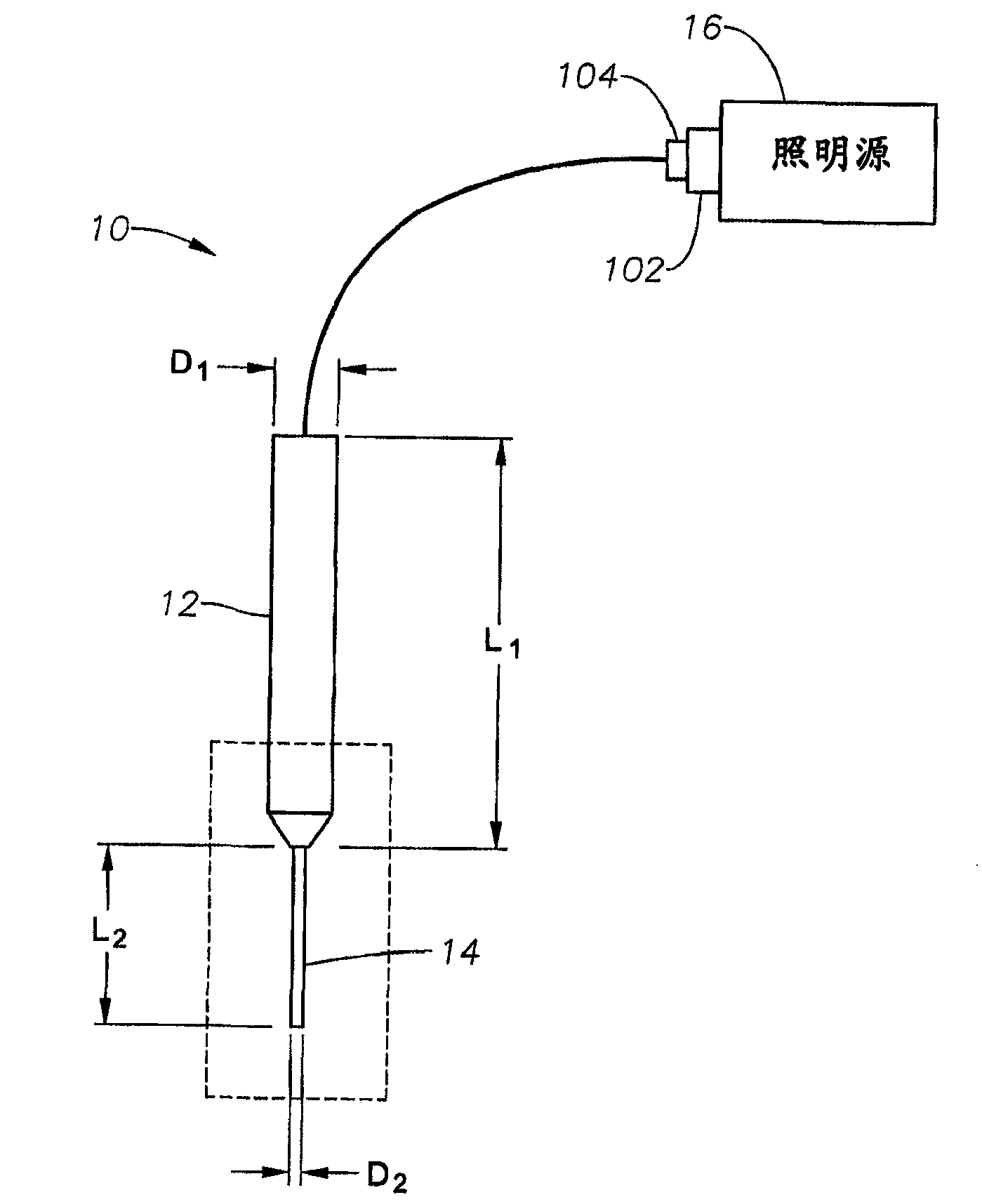
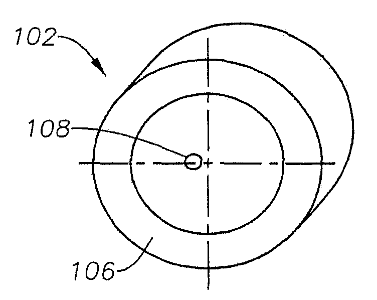
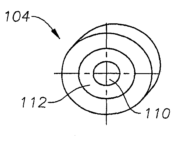
[0014] Various embodiments of the present invention provide a fiber optic connector system for off-center launch of a beam into a probe fiber. Certain embodiments include a source fiber optic connector and a probe fiber optic connector, wherein the illumination spot emanating from the source fiber optic connector is offset from the center of the probe fiber optic. For example, the connector may hold the central axes of the source emitter and probe fibers offset relative to each other. In another example, the source emitter may be configured to emit an illumination spot off-center relative to the probe fiber. Additional features of various embodiments of the invention are described in the following explanation of the figures.

[0015] Various embodiments of the present invention provide improved internal illumination by using off-center emission to increase the angular distribution of the illuminated area while providing equal or greater coupling efficiency to the illumination...


PUM


Abstract

An endoilluminator system includes an endoilluminator probe and an illumination source. The endoilluminator probe includes a nano-scale optical fiber and a probe fiber connector, and the illumination source includes a source fiber connector. The illumination source is configured to produce an illumination spot at the source fiber connector having a diameter smaller than a diameter of a fiber core of the nano-scale optical fiber. The probe fiber connector and the source connector are configured when connected to align the illumination spot off-center relative to the nano-scale optical fiber such that the angular distribution of light emitted by the nano-scale optical fiber is increased relative to aligning the illumination spot at a center of the nano-scale optical fiber.

Description

[0001] related application [0002] This application requires August 9, 2011 Submitted U.S. provisional application serial number 61 / 521,450 priority, the contents of which are incorporated herein by reference. technical field [0003] Embodiments described herein relate to the field of microsurgical probes. More specifically, embodiments described herein relate to the field of endoillumination using off-center fiber optic launches. Background technique [0004] The field of microsurgical procedures is rapidly evolving. Typically, these procedures involve the use of probes that are able to reach the tissue being treated or diagnosed. Such procedures utilize an endoscopic surgical instrument with a probe coupled to a controller device in a remote console. Prior art probes are rather complex to operate, often requiring moving parts that operate using complex mechanical systems. In many cases, electric motors are included in the probe design. The cost of most prior art d...

Claims


Application Information

Patent Timeline
Patent Type & Authority Applications(China)
IPC IPC(8): A61B1/06A61B90/30
CPCA61B1/0017A61B3/0008A61B1/07A61B19/5202A61B2019/5206G02B6/3624G02B6/4206A61B90/30A61B2090/306F04C2270/041
Inventor M·J·亚德洛斯基M·帕帕克
Owner ALCON RES LTD
Learn More