Cleaning tool
A technology for cleaning tools and racks, which is applied in cleaning equipment, cleaning machinery, carpet cleaning, etc. It can solve problems such as unsatisfactory cleaning effect of mop buckets, achieve ideal dehydration effect, save labor in dehydration operation, and improve dehydration effect.
- Summary
- Abstract
- Description
- Claims
- Application Information
AI Technical Summary
Problems solved by technology
Method used
Image

Examples
Embodiment 1
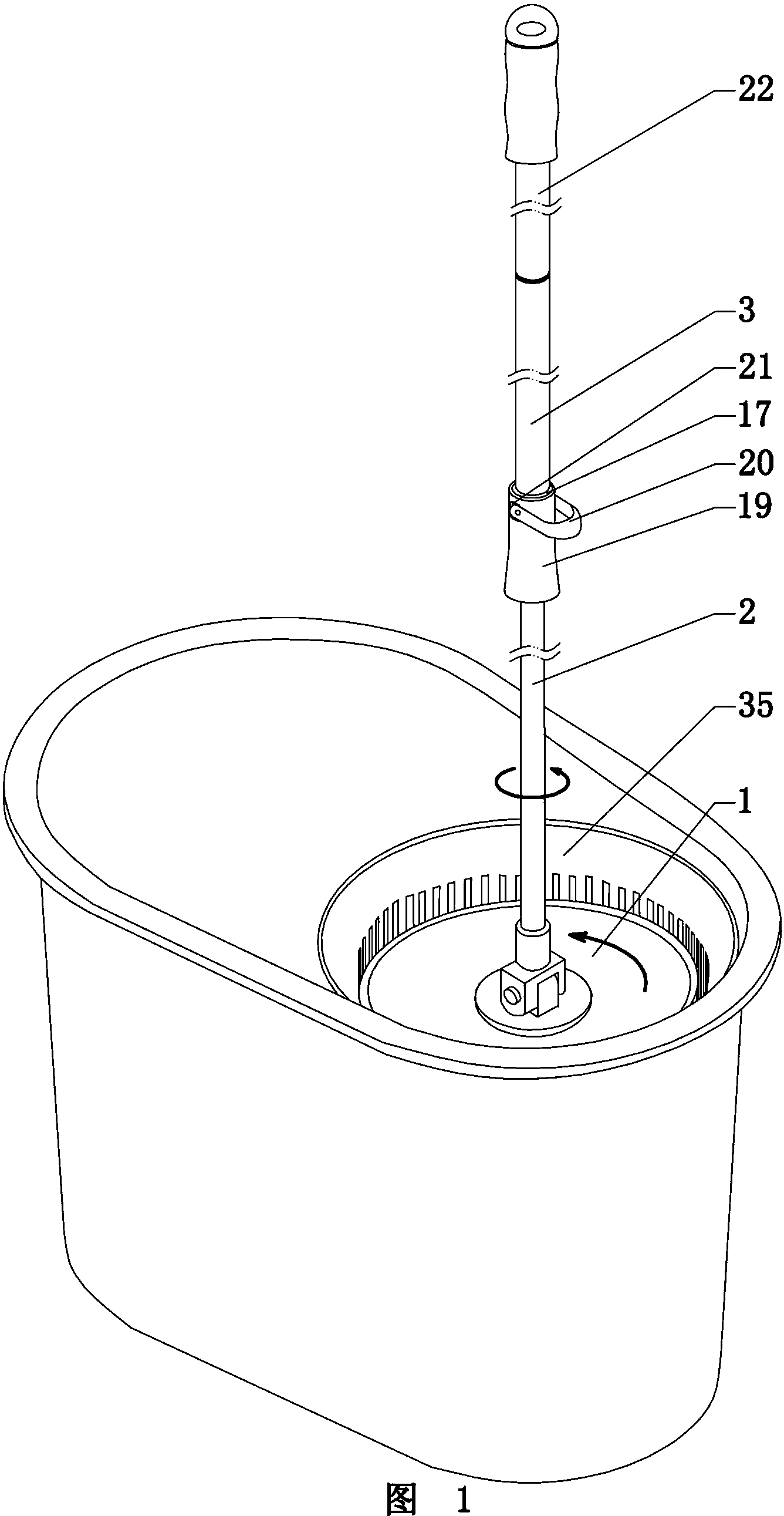
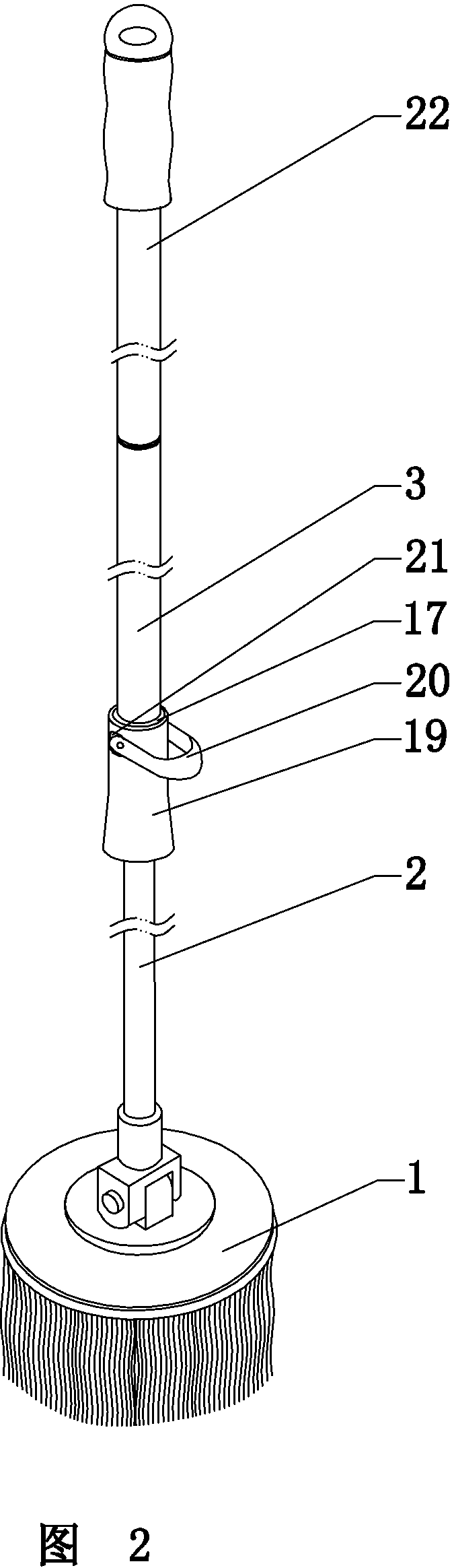
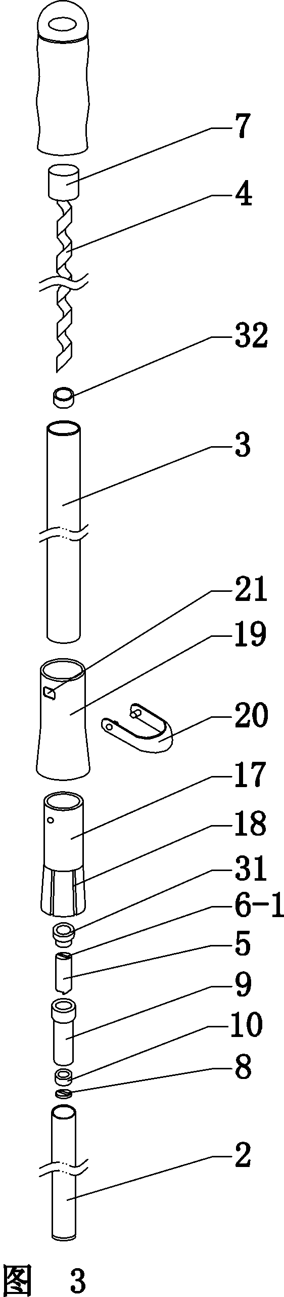
[0055] Figure 1-Figure 5 , Figure 15-Figure 17 Example 1 of the present invention is given. In the mop of this embodiment, the lower end of the mop rod is hinged with a mop head 1 with wipes. The mop rod at least includes an inner rod 2 and an outer rod 3. The inner and outer rods can be relatively rotated, and the mop rod can be shortened by socketing. and elongate, the lower end of the inner rod 2 is connected to the mop head 1; a driving mechanism is arranged between the inner and outer rods, and the driving mechanism drives the inner rod 2 and the mop head 1 to rotate. An elongated opening 6-1 matched with the screw rod is provided. An anti-pull-off mechanism is provided between the inner and outer rods, and the anti-pull-off mechanism includes: the screw rod part 4 is fixed to the outer rod 3 through the fixed end 7, and the screw rod part 4 is provided with a stopper 8. The inner rod is provided with a blocking sleeve, and in this embodiment, the blocking sleeve is ...
Embodiment 2
[0065] Figure 6 , Figure 7 Provides the second driving mechanism of the present invention to form one-way transmission and idling. In this embodiment, the outer rod 3 is the lower rod body connected with the mop head, and the inner rod 2 is the upper rod body. Such as Figure 6 As shown: the short mop rod is pressed down, the rotating sleeve is driven to rotate by the screw rod, and a one-way transmission is formed through the one-way transmission mechanism between the rotating sleeve and the inner rod, and the rod connected with the mop head and the mop head are driven to rotate. Such as Figure 7As shown: the mop rod is stretched upwards, the rotating sleeve is driven to rotate by the screw rod, and the one-way transmission mechanism makes the rotating sleeve and the inner rod form an idle rotation. All the others are basically the same as Embodiment 1, which can realize the object of the invention of the present invention equally.
Embodiment 3
[0067] Figure 8 , Figure 9 , Figure 10 Provides the third driving mechanism of the present invention to form one-way transmission and idling. In this embodiment, the inner rod 2 is the lower rod body connected with the mop head 1, and the outer rod 3 is the upper rod body. The one-way transmission mechanism includes: at least one slot 36 is provided on the periphery of the rotating sleeve 5, and a roller 37 or a rolling ball is arranged in the slot; , Roller or rolling ball and driving cover are stuck to form one-way transmission; Rotating cover another direction rotation compression roller 37 or rolling ball leave driving cover 9, form idling between rotating cover and driving cover. A thread 6-2 is arranged in the rotating sleeve 5, and the thread 6-2 cooperates with the screw member 4 to form a rotation. All the others are basically the same as Embodiment 1, which can realize the object of the invention of the present invention equally.
PUM
 Abstract
Description
Claims
Application Information
 - R&D Engineer
- R&D Manager
- IP Professional
- Industry Leading Data Capabilities
- Powerful AI technology
- Patent DNA Extraction
Browse by: Latest US Patents, China's latest patents, Technical Efficacy Thesaurus, Application Domain, Technology Topic.
© 2024 PatSnap. All rights reserved.Legal|Privacy policy|Modern Slavery Act Transparency Statement|Sitemap