Cooling device during shrinkage fit process of shaft parts

A technology of cooling device and shaft parts, which is applied in the field of shaft parts assembly, can solve the problems of reducing production efficiency, affecting assembly accuracy, and jamming in the assembly process of hole parts, so as to reduce production gaps, improve production efficiency, and avoid precision. effect of the problem

Active Publication Date: 2014-04-23
CNAIC CHENGDU AUTO PARTS
View PDF6 Cites 6 Cited by
  • Summary
  • Abstract
  • Description
  • Claims
  • Application Information

AI Technical Summary

Problems solved by technology

[0006] However, when at least two sets of hole parts need to be assembled on the same shaft, the following problems often occur when using the shrink fit method: when the first group of hole parts is heated and assembled on the shaft, the heat of the hole parts is quickly conducted To the shaft, the temperature of the shaft rises instantaneously and thermal expansion occurs, which offsets the assembly gap generated by the process due to the heating of the hole parts, resulting in the stagnation of the subsequent assembly process of the hole parts, and the assembly process cannot be completed smoothly
If this cooling method is used, cooling equipment using dry ice o

Method used


Image

  • Cooling device during shrinkage fit process of shaft parts
  • Cooling device during shrinkage fit process of shaft parts
  • Cooling device during shrinkage fit process of shaft parts

Examples


Embodiment approach

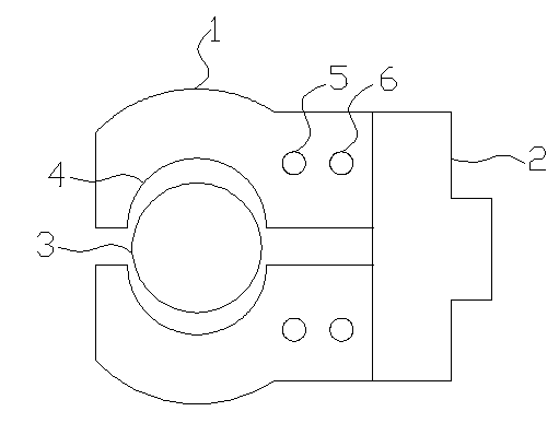
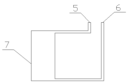
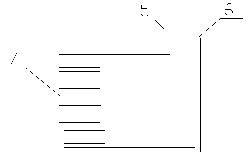
[0034] Such as figure 2As shown, this is a schematic diagram of the cooling water channel of the clamping arm. The cooling water coming in from the water inlet 5 enters the dense cooling water channel 7 that matches the shape of the clamping section (from the top view, if the clamping section is semicircular , then the dense cooling water channel 7 is a semi-circular ring whose radius is greater than that of the clamping section), where more cooling water can be collected to exchange heat with the clamping section, so as to achieve the purpose of rapidly cooling the assembly shaft; image 3 As shown, this is the schematic diagram b of the cooling water channel of the clamping arm. The cooling water coming in from the water inlet 5 enters the dense cooling water channel 7 of the clamping section. The dense cooling water channel 7 here is a snake perpendicular to the axial direction of the assembly axis. In order to achieve a better effect, this serpentine cooling channel match...


PUM


Abstract

The invention discloses a cooling device during shrinkage fit process of shaft parts, and belongs to the field of shaft part assembly. The cooling device comprises two clamping arms on the left and the right and a driving mechanism used for driving the clamping arms to close and open. Clamping parts are arranged on the clamping arms, the shape of the clamping parts matches with the shape of the shaft parts, and cooling water channels are arranged inside the clamping arms. The cooling device is simple in structure, high in accuracy, low in production cost and low in energy consumption, and is capable of rapidly cooling assembling shafts of the shaft parts in the same position during shrinkage fit assembling process, so that resetting errors of the assembling shafts caused by several movement and clamping during the cooling process are avoided, assembling accuracy is increased, production period is shortened and production efficiency is improved.

Description

[0001] technical field [0002] The invention belongs to the field of assembly of shaft parts, and in particular relates to a cooling device in the heat sleeve process of shaft parts. Background technique [0003] Shaft parts are one of the typical parts often encountered in hardware accessories. They are mainly used to support transmission parts, transmit torque and bear loads. The assembly of shaft parts (such as camshafts, gear shafts, drive shafts, etc.) (such as cams, gears, drive heads, etc.) is a kind of hole parts, and the method of interference assembly between hole parts and shafts is generally direct press fitting method and thermal sleeve method. [0004] When the direct press-fitting method is used for assembly, one end of the shaft is opposed to the port of the inner cavity of the hole type part, and then pressure equipment is used to apply pressure from the other end of the shaft along the assembly direction to force the shaft to be pressed into the inner...

Claims


Application Information

Patent Timeline
IPC IPC(8): B23P11/02
CPCB23P11/025
Inventor 余超
Owner CNAIC CHENGDU AUTO PARTS
Why Eureka
Try Eureka