
Double-color injection mold for pipe clamp of automobile circuit wire

An automotive circuit, two-color injection molding technology, applied in the field of injection molds, can solve the problems of low production efficiency, large mold cost investment, etc.

Active Publication Date: 2014-04-23
浙江正立塑模有限公司
View PDF4 Cites 8 Cited by
  • Summary
  • Abstract
  • Description
  • Claims
  • Application Information

AI Technical Summary

Problems solved by technology

[0002] Injection molds are used to produce pipe clips for automobile circuit wires. The pipe clips are fixed on the automobile engine, and the automobile circuit wires are clamped by the pipe clips. In order to distinguish the wires with different functions, the pipe clips are generally made of two colors. The existing technology uses secondary Injection molding, that is, two sets of molds are used. The first set of molds first injects the tube clamp blank of the first color, and then uses the tube clamp blank as an insert and puts it into the second set of molds for secondary injection molding. The disadvantages are: : The cost of the mold is large and the production efficiency is low

Method used


Image

  • Double-color injection mold for pipe clamp of automobile circuit wire
  • Double-color injection mold for pipe clamp of automobile circuit wire

Examples


Embodiment Construction

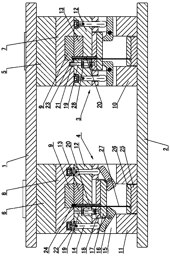
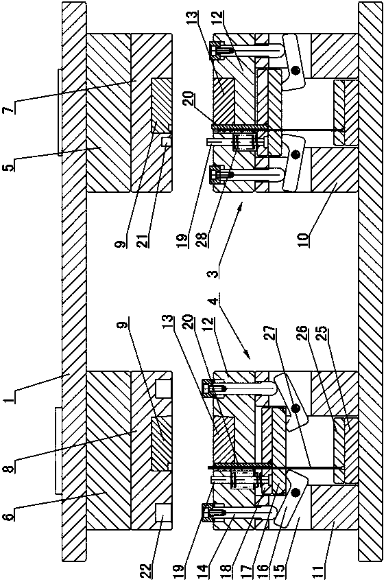
[0009] The invention relates to a two-color injection mold for automobile circuit wire pipe clips, such as figure 1 , figure 2 As shown, the mold includes an upper template 1 and a lower template 2, and a first injection mold 3 and a second injection mold 4 are arranged between the upper template 1 and the lower template 2, and the first injection mold 3 and the second injection mold The mold 4 is composed of a fixed mold part of the mold and a movable mold part of the mold. The fixed mold part includes a first pad 5 and a second pad 6 installed under the upper template 1, and the first pad 5 is installed under the The first fixed template 7, the second fixed template 8 is installed under the second pad 6, the fixed mold insert 9 is installed in the first fixed template 7 and the second fixed template 8, and the movable mold part is included on the lower template 2 Two first mold feet 10 and second mold feet 11 are respectively installed, and movable templates 12 are install...


PUM


Abstract

The invention discloses a double-color injection mold for a pipe clamp of an automobile circuit wire. The double-color injection mold comprises an upper mold plate and a lower mold plate, wherein a first injection mold and a second injection mold are arranged between the upper mold plate and the lower mold plate and comprise a first fixed mold plate and a second fixed mold plate which are respectively internally provided with a fixed mold insert; the lower mold plate is respectively provided with first mold feet and second mold feet; the first mold feet and the second mold feet are respectively provided with a movable mold plate; the movable mold plates are respectively internally provided with a movable mold insert and a pressing column; the first mold feet and the second mold feet are respectively internally provided with an avoiding groove which is internally provided with a prying rod; each prying rod is provided with a lower pushing plate and an upper pushing plate; each upper pushing plate is provided with a top column and an insert rod; the first fixed mold plate is provided with a top-column concave opening; the second fixed mold plate is provided with a pressing-column concave opening; the top column is matched with the top-column concave opening; one insert rod, the corresponding fixed mold insert and the corresponding movable mold insert form a first injection mold cavity; the pressing column is matched with the pressing-column concave opening; after the insert rods are withdrawn, the formed space is a second injection mold cavity, and by secondary injection molding with a mold blank, the complete product is formed.

Description

technical field [0001] The invention relates to a two-color injection mold used for producing automobile circuit conductor pipe clips, belonging to the field of injection molds. Background technique [0002] Injection molds are used to produce pipe clips for automobile circuit wires. The pipe clips are fixed on the automobile engine, and the automobile circuit wires are clamped by the pipe clips. In order to distinguish the wires with different functions, the pipe clips are generally made of two colors. The existing technology uses secondary Injection molding, that is, two sets of molds are used. The first set of molds first injects the tube clamp blank of the first color, and then uses the tube clamp blank as an insert and puts it into the second set of molds for secondary injection molding. The disadvantages are: : The cost of the mold is large and the production efficiency is low. Contents of the invention [0003] The purpose of the present invention is to overcome th...

Claims


Application Information

Patent Timeline
IPC IPC(8): B29C45/26B29C45/16B29C45/64
CPCB29C45/1615B29C45/1635B29C45/2602B29C45/2681B29C45/33
Inventor 黄正军潘建永陈承能叶丽群
Owner 浙江正立塑模有限公司
Learn More