Bidirectional auto-cascade heat pump system
A heat pump system, self-stacking technology, applied in heat pumps, lighting and heating equipment, damage protection, etc., can solve problems such as unfavorable long-term use of heat pumps, increased compressor exhaust temperature, and reduced heating efficiency.
- Summary
- Abstract
- Description
- Claims
- Application Information
AI Technical Summary
Problems solved by technology
Method used
Image
Examples
Embodiment 1
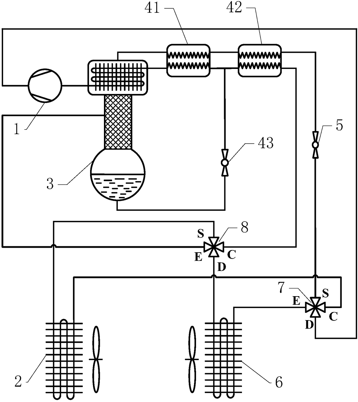
[0017] see figure 1 , the two-way self-cascading heat pump system includes a compressor 1, an indoor heat exchanger 2, a rectification column 3, a first regenerator 41, a second regenerator 42, and a secondary throttling device 43 connected between ports through pipelines , the main throttling device 5, the outdoor heat exchanger 6, the first four-way valve 7 and the second four-way valve 8; they work based on non-azeotropic mixed working fluid.
[0018] The D port of the first four-way valve 7 communicates with the outlet of the compressor 1, the S port communicates with the outlet of the main throttling device 5, the E port communicates with the inlet of the outdoor heat exchanger 6, and the C port communicates with the indoor heat exchange The inlet port of device 2 is connected.
[0019] The D port of the second four-way valve 8 communicates with the outlet of the outdoor heat exchanger 6, the S port communicates with the outlet of the indoor heat exchanger 2, the E port ...
Embodiment 2
[0027] As a description of Embodiment 2 of the present invention, only the differences from Embodiment 1 above will be described below.
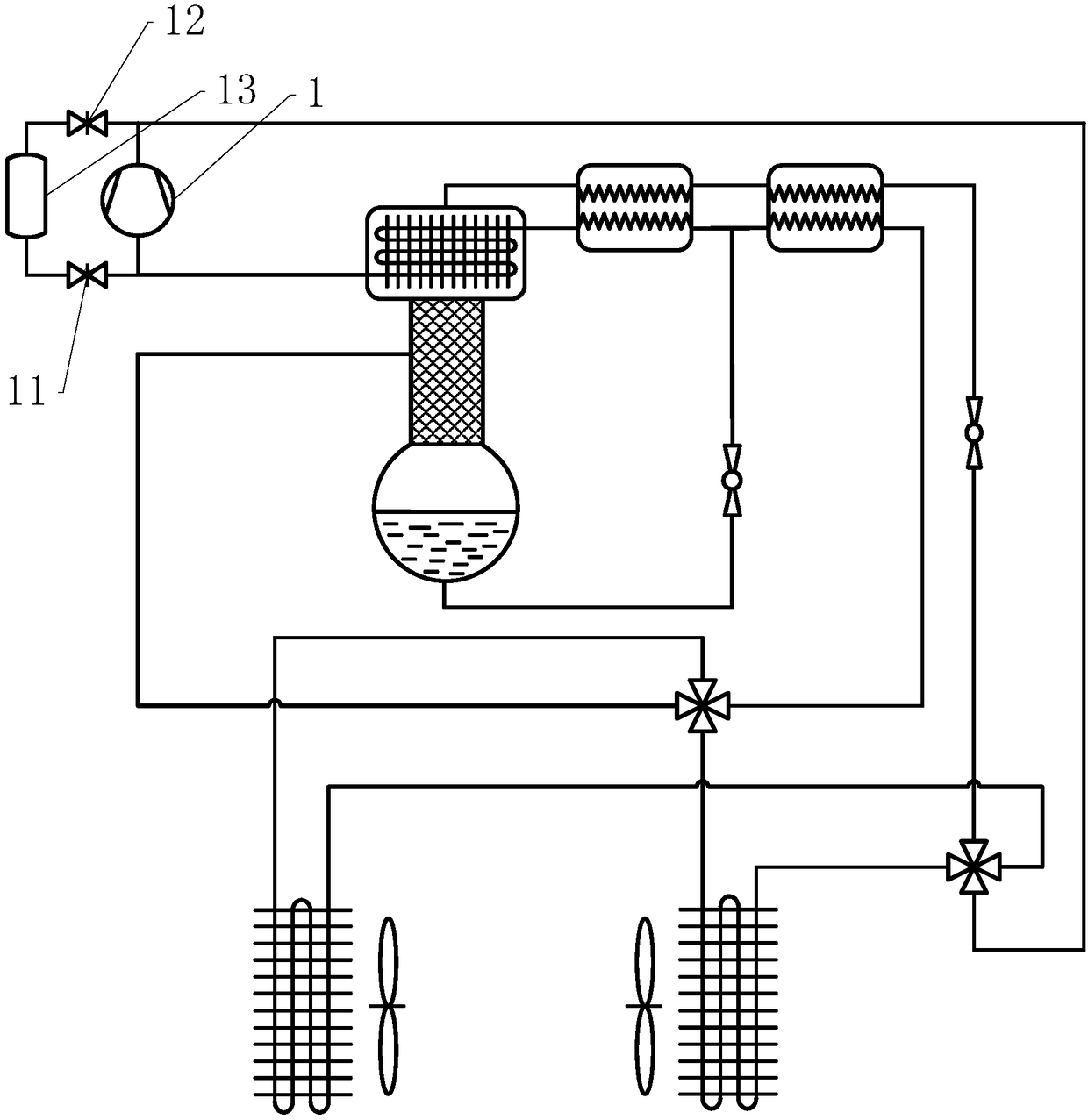
[0028] see figure 2 The two ends of the compressor 1 are connected in parallel with a start-up protection pipeline, the start-up protection pipeline includes an air storage tank 13, one end of the air storage tank 13 communicates with the inlet end of the compressor 1 through a stop valve 11, and the other end passes through a stop valve 12 communicates with the outlet port of the compressor 1. During operation, the two ports of the compressor 1 are bypassed by controlling the opening and closing states of the shut-off valves 11 and 12, so that the compressor 1 starts under low pressure load.
Embodiment 3
[0030] As an explanation of Embodiment 3 of the present invention, only the differences from Embodiment 1 above will be described below.
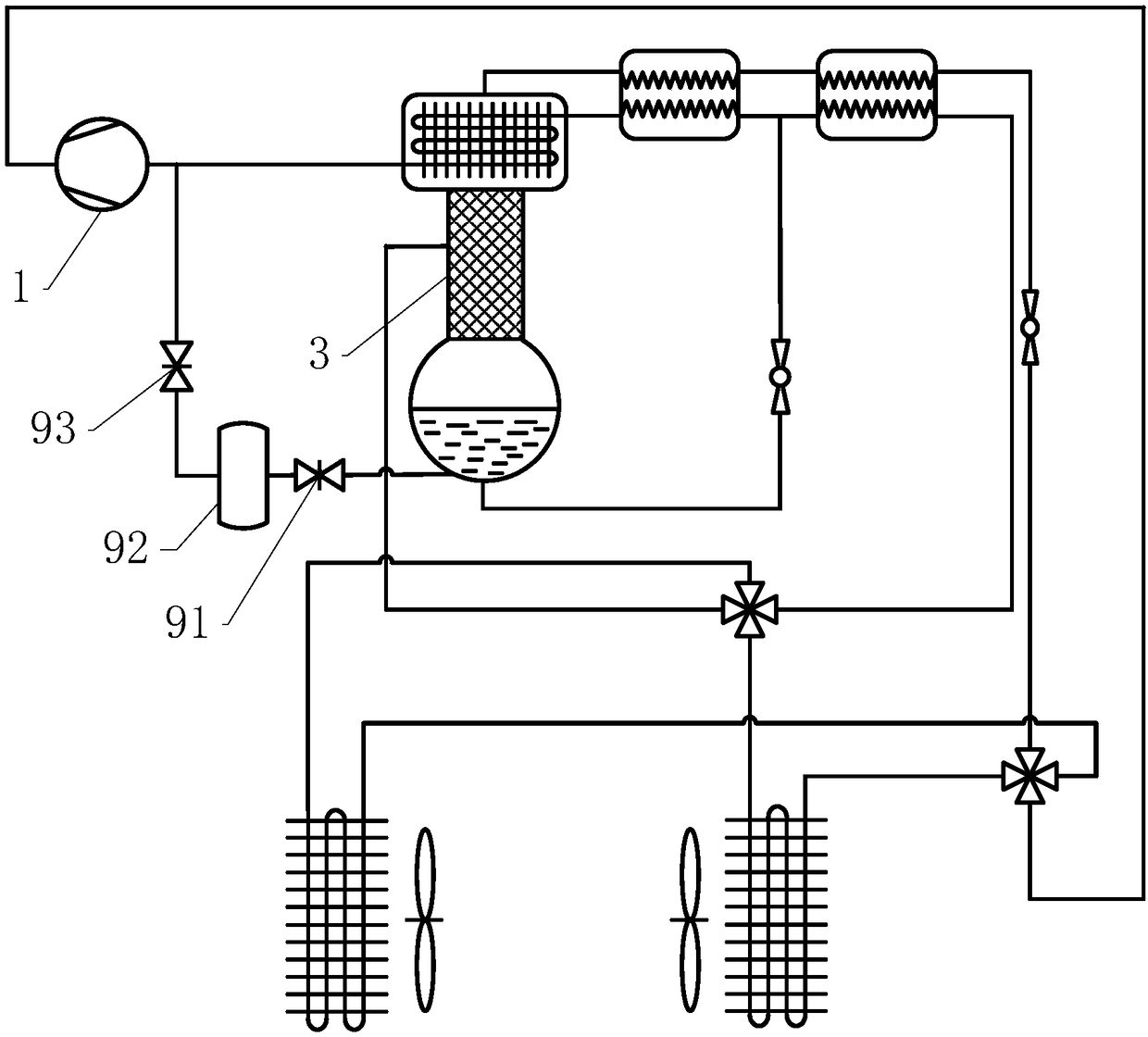
[0031] see image 3 , between the rectification column 3 and the compressor 1, there is a separate storage pipeline, which includes a liquid storage tank 92, and one end of the liquid storage tank 92 passes through the stop valve 91 and the bottom drain port of the rectification column 3 The other end communicates with the inlet end of the compressor 1 through the shut-off valve 93. Through the control of the opening and closing states of the two stop valves, when the working fluid in the circuit is excessive, part of the working fluid is stored; when the working fluid is insufficient, the working fluid is filled into the circuit to ensure the operating efficiency of the circuit. In addition, what is stored at the bottom of the rectification column is mainly the high-boiling point components in the mixed working fluid, so that the liquid s...
PUM
 Abstract
Description
Claims
Application Information
 - R&D
- Intellectual Property
- Life Sciences
- Materials
- Tech Scout
- Unparalleled Data Quality
- Higher Quality Content
- 60% Fewer Hallucinations
Browse by: Latest US Patents, China's latest patents, Technical Efficacy Thesaurus, Application Domain, Technology Topic, Popular Technical Reports.
© 2025 PatSnap. All rights reserved.Legal|Privacy policy|Modern Slavery Act Transparency Statement|Sitemap|About US| Contact US: help@patsnap.com


