Wire harness feeding mechanism

A conveying mechanism and wire feeding technology, applied in the direction of conveying filamentous materials, thin material handling, transportation and packaging, etc., can solve the problems of increasing the burden on enterprises, breaking the wire harness, and increasing the production cost of wires, and achieves safe and stable operation and use. High reliability and smooth wire transportation

Inactive Publication Date: 2014-04-23
KUNSHAN FOR EASIER AUTOMATION TECH
View PDF0 Cites 5 Cited by
  • Summary
  • Abstract
  • Description
  • Claims
  • Application Information

AI Technical Summary

Problems solved by technology

[0003] In order to solve the problem that the pay-off frame in the prior art only has the function of paying off wires, the tension degree of the wire rods during the conveying process cannot be well known, and the friction coefficient between the wire rods and the wire rod tensioning shaft is relatively large, which easily leads to the breakage of the wire bundles, causing serious damage to the follow-up The processing and production have a great impact, and the broken wire also increases the production cost of the enterprise and increases the burden on the enterprise. The invention provides a simple structure, easy to use, which can detect the tension of the wire and prompt the operator. Loosen wire harness feeding mechanism for wire rod

Method used


Image

  • Wire harness feeding mechanism
  • Wire harness feeding mechanism

Examples


Embodiment Construction

[0015] Below in conjunction with accompanying drawing, the present invention will be further described:

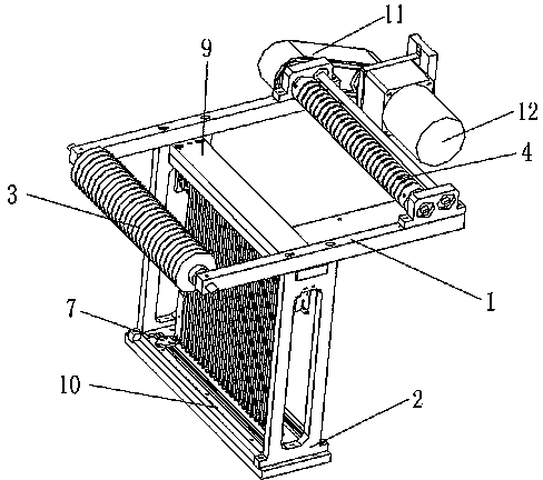
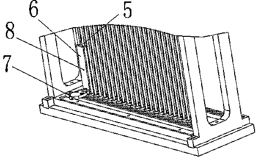
[0016] Such as Figure 1-2 As shown, a wiring harness wire feeding mechanism includes a horizontal frame 1, a vertical protection frame 2, a front wire tensioning shaft 3, a rear wire tensioning shaft 4, several vertical columns 5, a wire passing plate 6, an inductor 7, The motor 12 and the conveying mechanism are respectively connected with a front wire tensioning shaft 3 and a rear wire tensioning shaft 4 at the front and rear of the horizontal frame 1, and a vertical protective frame 2 is connected below the middle of the horizontal frame 1, and the vertical Two rows of vertical columns 5 are arranged between the upper connection plate 9 and the lower connection plate 10 on the protection frame 2, each row of vertical columns 5 includes twenty-six vertical columns, and the two rows of vertical columns 5 are arranged at intervals .

[0017] The wire passing board 6 is ...


PUM


Abstract

The invention discloses a wire harness feeding mechanism which comprises a horizontal frame and a vertical protection frame and is characterized in that a front wire tensioning shaft and a rear wire tensioning shaft are connected onto the front portion and the rear portion of the horizontal frame, the vertical protection frame is connected under the middle of the horizontal frame, a plurality of vertical columns are arranged between the upper connection plate and the lower connection plate of the vertical protection frame, a wire through plate is arranged on the vertical columns, a wire through hole is formed in the wire through plate, an inductor is arranged on the lower connection plate of the vertical protection frame, a motor is arranged beside the rear wire tensioning shaft, and the motor drives the rear wire tensioning shaft to rotate through a conveying mechanism. The wire harness feeding mechanism solves the problem that an unwinding support only has an unwinding function, a wire is easy to break due to the fact that the friction coefficient between the wire and the wire tensioning shafts is large, and the broken wire increases the production cost of enterprises. The mechanism is simple in structure, convenient to use and capable of detecting wire tensioning degree and prompting an operator to loose the wire.

Description

technical field [0001] The invention relates to a wire harness feeding mechanism, in particular to a wire harness feeding mechanism. Background technique [0002] At present, when the wire harness is sent to manufacture the wire harness, the wire rack only has the wire-releasing function, and the tension degree of the wire harness during the conveying process cannot be well known. If the wire harness is too tense, it is easy to cause the wire harness to break, which will bring great harm to the subsequent processing and production. It will have a greater impact, and the broken wire harness will also increase the production cost of the enterprise and increase the burden on the enterprise. At the same time, the current wire rod tensioning shaft is fixed on the equipment and cannot be rotated, so the friction coefficient between the wire rod and the wire rod tensioning shaft is relatively large, and it is easy to break the wire rod, causing damage to the wire rod and bringing g...

Claims


Application Information

Patent Timeline
Patent Type & Authority Applications(China)
IPC IPC(8): B65H57/02B65H57/28B65H59/00B65H59/40B65H51/32B65H51/06B65H63/02
Inventor 侯斌曹洪胜郭池洪
Owner KUNSHAN FOR EASIER AUTOMATION TECH
Why Eureka
Try Eureka