Eureka AIR delivers breakthrough ideas for toughest innovation challenges, trusted by R&D personnel around the world.

Groundwater recharge system structure for foundation pit dewatering

A system structure, groundwater technology, applied in infrastructure engineering, soil protection, construction, etc., can solve problems such as blockage, and achieve the effect of reducing land subsidence, restraining land subsidence, and reducing underground obstacles

Inactive Publication Date: 2014-04-23
SHANGHAI CHANGKAI GEOTECHN ENG
View PDF4 Cites 25 Cited by
  • Summary
  • Abstract
  • Description
  • Claims
  • Application Information

AI Technical Summary

Problems solved by technology

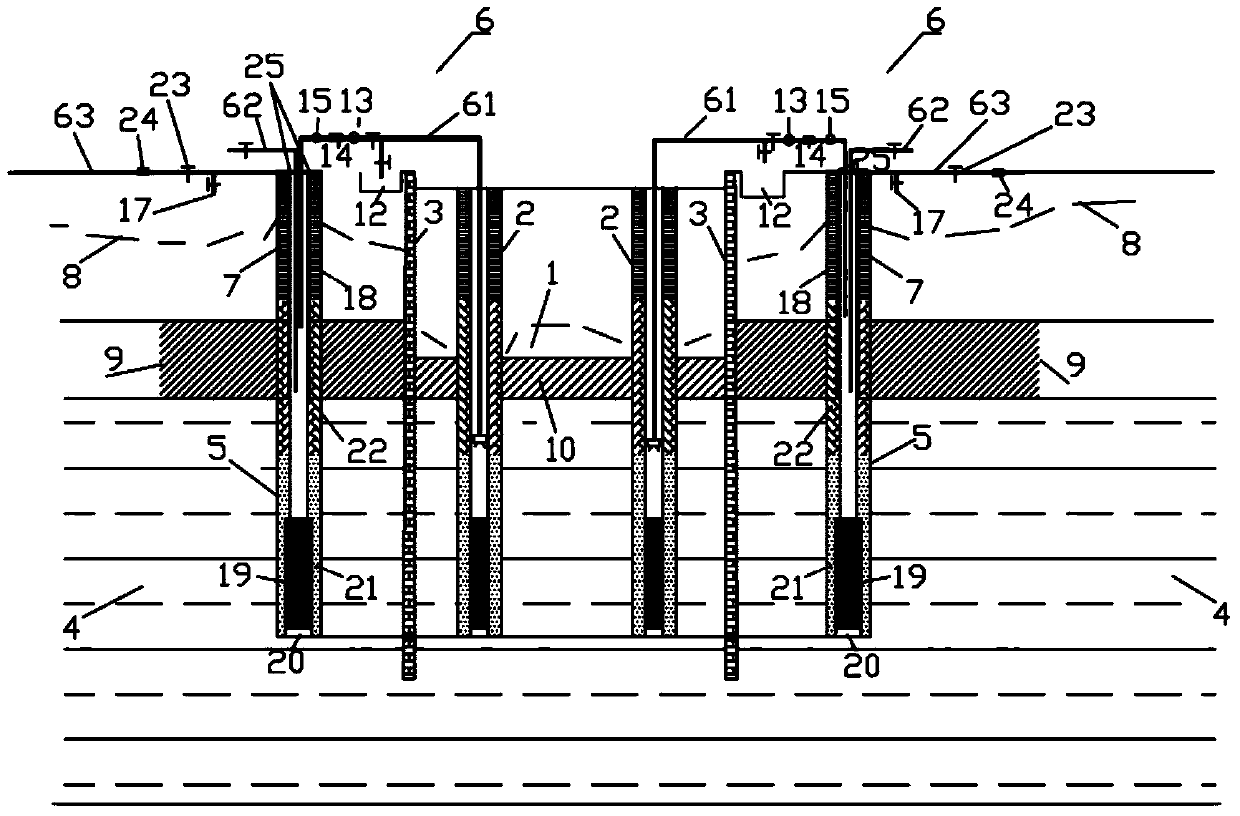
[0005] The purpose of the present invention is to provide a groundwater recharge system structure used in foundation pit dewatering, which can reduce and slow down the surrounding stratum settlement and ground subsidence caused by foundation pit dewatering in the stat

Method used


Image

  • Groundwater recharge system structure for foundation pit dewatering
  • Groundwater recharge system structure for foundation pit dewatering

Examples


Embodiment Construction

[0021] Such as figure 1 The shown structure of the groundwater recharge system used in the foundation pit dewatering includes the recharge well 5 and the recharge device, and a water-stop curtain 3 is provided on the edge of the foundation pit 1, and the water-stop curtain 3 is partially inserted into the confined aquifer In 4, as the enclosure of the foundation pit 1, the decompression well 2 is set inside the water-stop curtain 3, and the reinjection well 5 is set outside the water-stop curtain 3. The water is connected, and the bottoms of the depressurization well 2 and the reinjection well 5 are respectively provided with filters, and the bottoms of the filters are shallower than the bottoms of the water-stop curtain 3 .

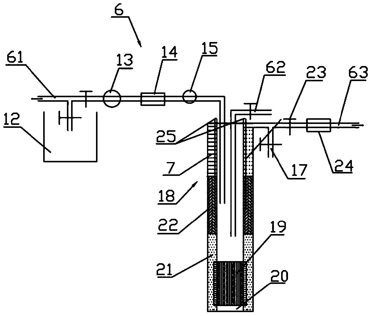
[0022] combine figure 2 As shown, the reinjection well 5 includes: a well pipe 18, and the outer wall of the well pipe 18 is provided with a water-stop layer 7, a water-resistant layer 22 and a filter layer 21 sequentially from top to bottom, wherein t...


PUM

PropertyMeasurementUnit
Diameteraaaaaaaaaa
Diameteraaaaaaaaaa
Thicknessaaaaaaaaaa

Abstract

The invention relates to a groundwater recharge system structure for foundation pit dewatering. The purpose of the invention is to provide a groundwater recharge system structure for foundation pit dewatering which is capable of reducing and retarding surrounding stratum settlement and ground settlement caused by foundation pit dewatering under the state of an enormously thick confined aquifer, and simultaneously capable of overcoming the shortcomings such as recharge well blockage and water outflowing at the outer side in the prior art, improving the recharge efficiency and also prolonging the service life of the recharge system. The groundwater recharge system structure is matched with a foundation pit depressurizing system in use, and comprises a recharge well and a recharge device, wherein the recharge well comprises a well pipe; a water stop layer, a water-resisting layer and a filter layer are orderly arranged on the outer wall of the well pipe from top to bottom, a mudjacking pipe is reserved outside the well pipe, a sedimentation pipe is arranged at the bottom of the well pipe, a two-layer wind filter is arranged at the upper part of the sedimentation pipe, and a water suction pump is arranged in the well pipe 2-6m away from the bottom of the well, and the like; the recharge device comprises a recharge pipeline, a water release pipeline, an exhaust pipeline and the like.

Description

technical field [0001] The invention relates to the technical field of foundation pit engineering in geotechnical engineering in the field of municipal and construction engineering, and specifically relates to a groundwater recharge system structure used in foundation pit dewatering. Background technique [0002] Foundation pit engineering is a general term for engineering measures such as enclosure, support, precipitation, reinforcement, excavation and backfilling to excavate the earthwork at the underground structure of the project and ensure the safety of the foundation pit and the surrounding environment. Foundation pit dewatering is an engineering method that bury well pipes inside and outside the foundation pit and use mechanical equipment to pump water to reduce the groundwater level. Groundwater control refers to measures such as drainage, precipitation, water stop or recharge for the construction of foundation pit engineering and to reduce the impact on the surround...

Claims


Application Information

Patent Timeline
IPC IPC(8): E02D3/10
Inventor 瞿成松
Owner SHANGHAI CHANGKAI GEOTECHN ENG
Why Eureka
Eureka Blog
Learn More