Axial vibrator

An axial vibration, outer cylinder technology, applied in the direction of drilling with vibration, etc., to achieve the effect of reliable vibration, simple structure and strong adaptability

Active Publication Date: 2014-04-23
中国石油集团川庆钻探工程有限公司长庆钻井总公司
View PDF6 Cites 13 Cited by
  • Summary
  • Abstract
  • Description
  • Claims
  • Application Information

AI Technical Summary

Problems solved by technology

In the domestic drilling market, there is no domestically-made stereotyped drilling tool that adopts the mechanical vibration method and has been put into production

Method used


Image

  • Axial vibrator

Examples


Embodiment Construction

[0014] Below in conjunction with accompanying drawing, the present invention is described in further detail:

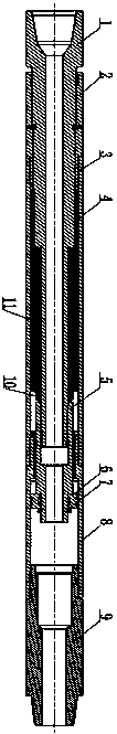
[0015] Such as figure 1 As shown, the present invention provides an axial vibrator, which includes an upper connecting central rod 1, an inner spline cylinder 2, an outer cylinder 3, a lower outer cylinder 8 and a lower joint 9, and the upper connecting central rod 1 extends into the inner spline cylinder 2 and its front end are threaded, the rear end of the inner spline cylinder 2 is threaded with the front end of the outer cylinder 3, the rear end of the outer cylinder 3 is threaded with the front end of the lower outer cylinder 8, the rear end of the lower outer cylinder 8 is threaded with the lower joint 9, The lower joint 9 is a thread conversion joint; the tail end of the upper connection center rod 1 is threadedly connected with the front end of the lower joint 5 of the central pipe; a group of butterfly spring groups 11 are also set between the upper connectio...


PUM


Abstract

The axial vibrator belongs to the field of drilling tools, in particular to an axial vibrator. The axial vibrator can produce an axial vibrating through adopting pressure pulses produced by a circumferential vibrator or a pulser to effectively solve the pulling problem of drill string of high angle extended-reach wells and horizontal wells. The axial vibrator is simple in structure and reliable in vibrating. The pulser can be replaced and pressure oscillation of slurry can be changed; therefore, the vibration power can be adjusted and the adjustability is strong.

Description

technical field [0001] The invention belongs to the field of drilling tools, in particular to an axial vibrator. Background technique [0002] In the drilling operations of directional wells, horizontal wells, extended-reach wells and lateral wells, due to the curvature or dogleg of the wellbore trajectory, the drill string forms contact (or underpinning) with the lower side of the wellbore below the curved well section, thus As a result, the pressure on bit cannot be effectively applied, resulting in back pressure. Once the supporting pressure effect occurs, the drilling speed will be greatly reduced, creating unsafe hazards and increasing the risk of drilling operations. The solution to the underpinning effect in complex well drilling is an important basic theoretical topic in the field of petroleum drilling science in the world. At present, the previous achievements in the international drilling field on alleviating the back pressure effect in drill string sliding drill...

Claims


Application Information

Patent Timeline
Patent Type & Authority Applications(China)
IPC IPC(8): E21B7/24
Inventor 宋顺平易先中杨森陈霖王力宏李培梅王武
Owner 中国石油集团川庆钻探工程有限公司长庆钻井总公司
Why Eureka
Try Eureka