
Cross-flow cooling tower

A cooling tower, cross-flow technology, applied in water shower coolers, direct contact heat exchangers, heat exchanger types, etc., can solve the problems of reduced cooling effect, large system resistance, and high system effect value, and achieve air Minimized flow resistance, reduced separation and shedding, compact and simple structure

Inactive Publication Date: 2014-04-23
浙江舜祥环境科技有限公司
View PDF4 Cites 5 Cited by
  • Summary
  • Abstract
  • Description
  • Claims
  • Application Information

AI Technical Summary

Problems solved by technology

[0002] The single-side air inlet cooling tower on the market adopts the structure of drawing air at the top or side of the tower. The air enters through the side of the filler to exchange heat and mass with hot water, and the hot and humid air is discharged to the outside of the tower. This structure cooling tower is suitable for application In underground buildings (such as subway projects), due to the small surrounding space and obstacles, there is a difference in the flow field between the front and back of the cooling tower fan, resulting in the disadvantages of high system effect influence value, large system resistance, high energy consumption, and low cooling efficiency
Usually, the land in large and medium-sized cities is very expensive, and cooling towers in many underground construction projects are required to be placed underground, and greenery is planted on the top of the cooling tower. This unreasonable design still exists and has not been improved. Conventional cooling towers can only be installed on the ground. If they are used underground, there will be disadvantages such as poorer ventilation conditions and serious backflow of hot and humid air, and the cooling effect will be greatly reduced.

Method used


Image

  • Cross-flow cooling tower

Examples


Embodiment Construction

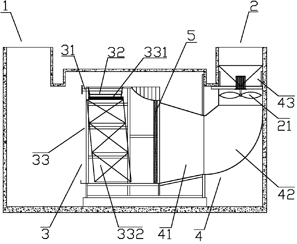
[0010] Such as figure 1 The present invention disclosed is a cross-flow cooling tower, which includes an air inlet 1 arranged at one end of the cooling tower, an air outlet 2 at the other end and a tower body 3 located in the cooling tower, and a water inlet pipe is arranged at the end of the air inlet 1 31, corresponding to the lower edge of the water inlet pipe 31, a water diffuser 32 is provided, and the lower side of the water diffuser 32 is provided with a packing device 33, and the water inlet pipe 31, the water diffuser 32 and the filler device 33 are all located in the tower body 3, and the tower One end of the body 3 is connected with a guide pipe 4, and the other end of the guide pipe 4 is connected with the air outlet 2 provided with a fan 21;

[0011] Further, the packing device 33 includes a redistribution packing 331 located on the lower side of the water distribution tray 32 and corresponding to the water distribution tray 32 and a packing 332 located on the low...


PUM


Abstract

The invention belongs to the heat exchange equipment, and specifically relates to a cross-flow cooling tower. The cooling tower comprises a wind inlet arranged on one end of the cooling tower, a wind outlet arranged on the other end of the cooling tower, and a tower body in the cooling tower; the wind inlet end is provided with a water inlet pipe, the lower edge of the water inlet pipe is correspondingly provided with a water dispersing disc, the lower side of the water dispersing disc is provided with a material feeding device; the water inlet pipe, the water dispersing disc, and the material feeding device are all arranged in the tower body, one end of the tower body is connected to a flow guiding pipe, the other end of the flow guiding pipe is connected to the wind outlet which is provided with a draught fan, and a water collecting device is arranged on the joint between the flow guiding pipe and the tower body. The cross-flow cooling tower has the advantages of simple structure, high heat-exchange efficiency, and environment-friendliness.

Description

technical field [0001] The invention belongs to heat exchange equipment, in particular to a cross-flow cooling tower. Background technique [0002] The single-side air inlet cooling tower on the market adopts the structure of drawing air at the top or side of the tower. The air enters through the side of the filler to exchange heat and mass with hot water, and the hot and humid air is discharged to the outside of the tower. This structure cooling tower is suitable for application In underground buildings (such as subway projects), due to the small surrounding space and obstacles, there is a difference in the flow field between the front and back of the cooling tower fan, resulting in the disadvantages of high system effect influence value, large system resistance, high energy consumption, and low cooling efficiency . Usually, the land in large and medium-sized cities is very expensive, and cooling towers in many underground construction projects are required to be placed un...

Claims


Application Information

Patent Timeline
Patent Type & Authority Applications(China)
IPC IPC(8): F28C1/00F28F25/12
Inventor 胡谷庆徐鑫祥曹阳章晶晶姚振雨
Owner 浙江舜祥环境科技有限公司
Learn More