
Method and device for measuring nano film

A nano-film and measurement method technology, applied in the field of optics, can solve problems such as the inability to obtain analytical solutions, doubts about the accuracy of the dispersion equation, and the loss of function of the dispersion-related spectroscopic ellipsometer, so as to achieve accurate and reliable measurement results and simplify the complexity of measurement. sexual effect

Active Publication Date: 2014-04-23
UNIV OF SCI & TECH OF CHINA
View PDF2 Cites 16 Cited by
  • Summary
  • Abstract
  • Description
  • Claims
  • Application Information

AI Technical Summary

Problems solved by technology

However, the traditional ellipsometric method for measuring thickness still has obvious defects: the ellipsometric equations based on the ellipsometric method are a set of transcendental equations, which cannot be solved analytically, and a physical model must first be established, and then the correct parameters of the model must be determined by the inversion method
However, different dispersion equations are applicable to samples of different properties, some samples may apply different dispersion equations in different wave bands or there is no suitable dispersion equation at all, which brings great difficulties to practical analysis
Due to the empirical nature of the dispersion equation, the accuracy of the dispersion equation applied to different samples is also facing doubts, especially for ultra-thin metal films with a thickness below 10nm, there is no completely suitable dispersion relationship to choose from, which leads to spectroscopic ellipsometer in this One area is basically useless

Method used


Image

  • Method and device for measuring nano film
  • Method and device for measuring nano film
  • Method and device for measuring nano film

Examples


Embodiment Construction

[0026] The technical solutions in the embodiments of the present invention will be clearly and completely described below in conjunction with the accompanying drawings in the embodiments of the present invention. Obviously, the described embodiments are only some of the embodiments of the present invention, not all of them. Based on the embodiments of the present invention, all other embodiments obtained by persons of ordinary skill in the art without making creative efforts belong to the protection scope of the present invention.

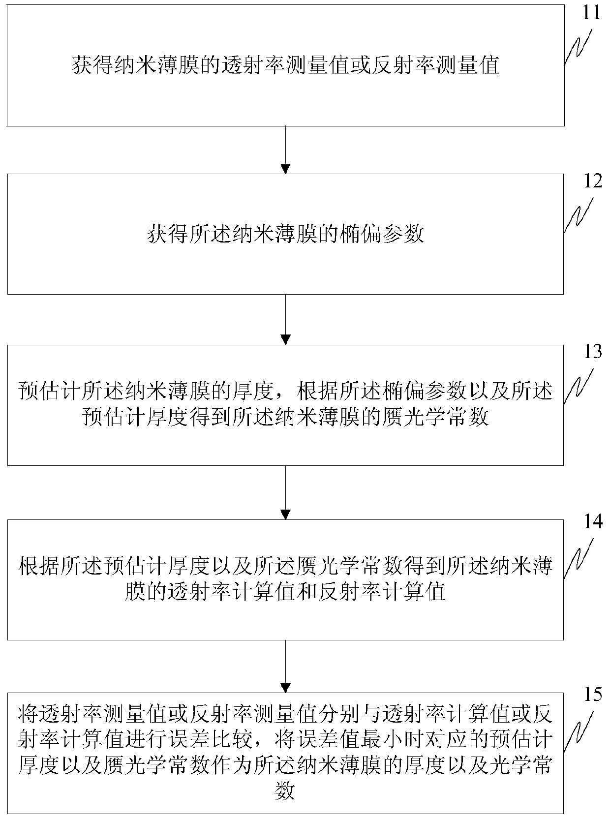
[0027] Such as figure 1 As shown, the embodiment of the present invention provides a method for measuring nano-films, including:

[0028] Step 11, obtaining the transmittance measurement value or the reflectance measurement value of the nano film.

[0029] Step 12, obtaining the ellipsometric parameters of the nano film.

[0030] Step 13, pre-estimating the thickness of the nano-film, and obtaining pseudo-optical constants of the nano-film accord...


PUM


Abstract

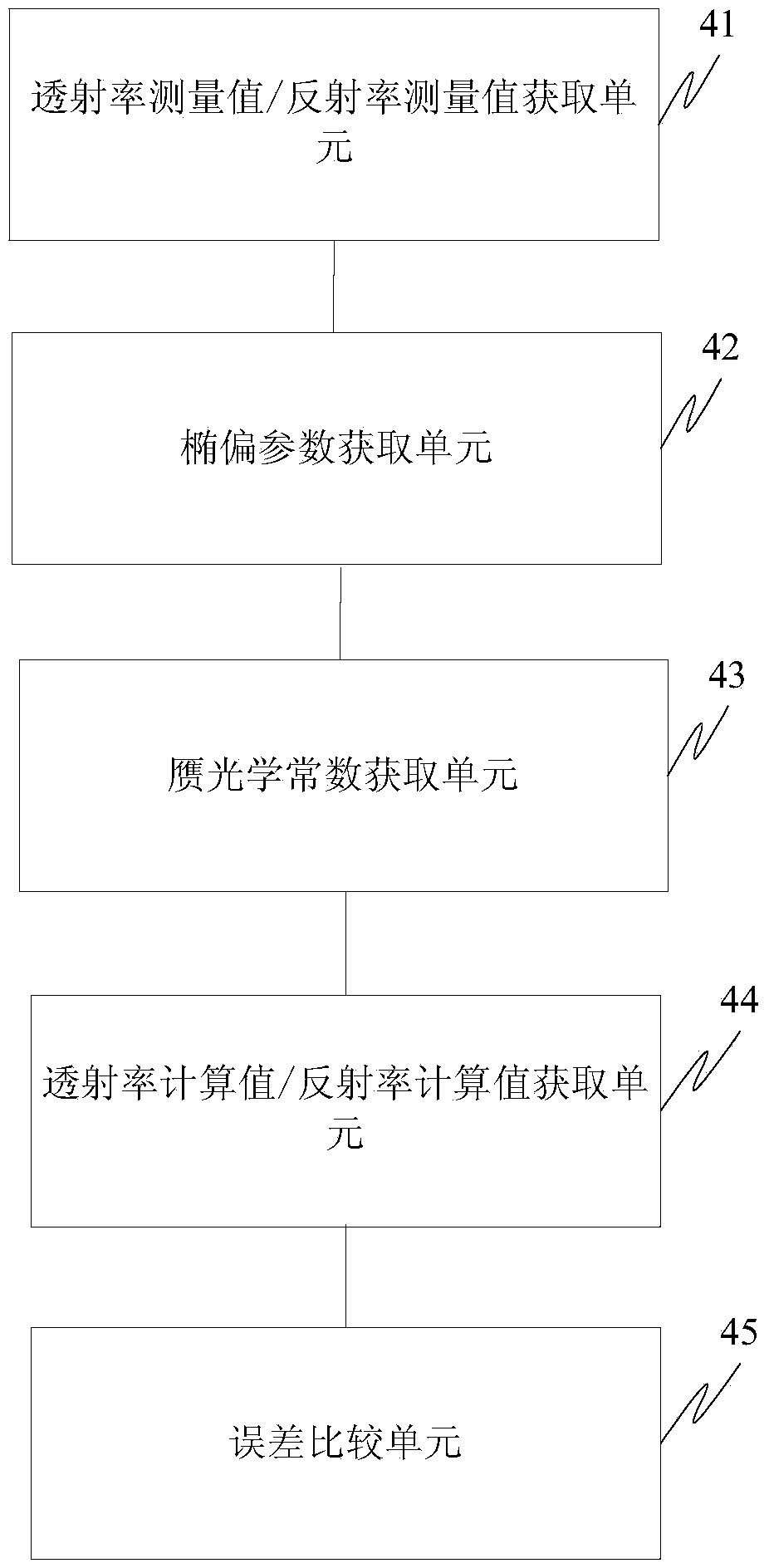
The invention discloses a method and a device for measuring a nano film. The method for measuring the nano film comprises the following steps of acquiring a transmittance measurement value or a reflectivity measurement value of the nano film; acquiring ellipsometry parameters of the nano film; estimating the thickness of the nano film, obtaining a pseudo optical constant of the nano film according to the ellipsometry parameter and the estimated thickness; obtaining a transmittance calculation value or a reflectivity calculation value of the nano film according to the estimated thickness and the pseudo optical constant; executing the error comparison for the transmittance measurement value or the reflectivity measurement value with the transmittance calculation value or the reflectivity calculation value, and utilizing the estimated thickness and the pseudo optical constant corresponding to the minimal error value as the thickness and optical constant of the nano film. By adopting the transmittance or reflectivity and the ellipsometry method to assist the analysis, the pseudo optical constant is introduced, and the data is processed by adopting a fitting algorithm and an iteration algorithm, so that the optical constant and thickness of a film sample can be precisely measured.

Description

technical field [0001] The invention relates to the field of optical technology, in particular to a method and device for measuring a nanometer thin film. Background technique [0002] Due to the unique optical, mechanical, chemical, electromagnetic and other characteristics of nano-film, it occupies an extremely important position in the field of modern optoelectronics industry. The wide application of nano-optical thin films has also led to higher and higher requirements for their optical properties and preparation processes, which are usually directly reflected in the precise control of their thickness and optical properties. Therefore, it is of great significance to accurately measure the thickness and optical constants of thin films for the study of the properties of nano thin films and the preparation of high-quality thin films. [0003] Due to its non-destructive, non-contact, high sensitivity, high precision, and real-time monitoring of ultra-thin films and their pr...

Claims


Application Information

Patent Timeline
IPC IPC(8): G01B11/06G01M11/02
Inventor 张增明宫俊波代如成王中平丁泽军
Owner UNIV OF SCI & TECH OF CHINA
Learn More