
Attitude sensor mounting offset correction method

A technology of attitude sensor and correction method, which is applied to measurement devices, instruments, surveying and mapping and navigation, etc., can solve problems such as inaccurate angular velocity measurement, and achieve the effects of high accuracy and reliability and low cost.

Inactive Publication Date: 2014-04-23
SHANGHAI NEW CENTURY ROBOT
View PDF7 Cites 10 Cited by
  • Summary
  • Abstract
  • Description
  • Claims
  • Application Information

AI Technical Summary

Problems solved by technology

[0007] In order to solve the problem of inaccurate measurement of the angular velocity of the self-balancing two-wheeled vehicle installation platform caused by the installation offset of the attitude sensor, the present invention provides a low-cost, high-accuracy and reliable correction method for the installation offset of the attitude sensor. It can effectively solve the problem of inaccurate angular velocity measurement caused by the installation offset of the attitude sensor

Method used


Image

  • Attitude sensor mounting offset correction method
  • Attitude sensor mounting offset correction method
  • Attitude sensor mounting offset correction method

Examples


Embodiment Construction

[0017] The method for correcting the installation offset of the attitude sensor of the present invention will be described in further detail below in conjunction with the accompanying drawings and specific embodiments, but it is not intended to limit the present invention.

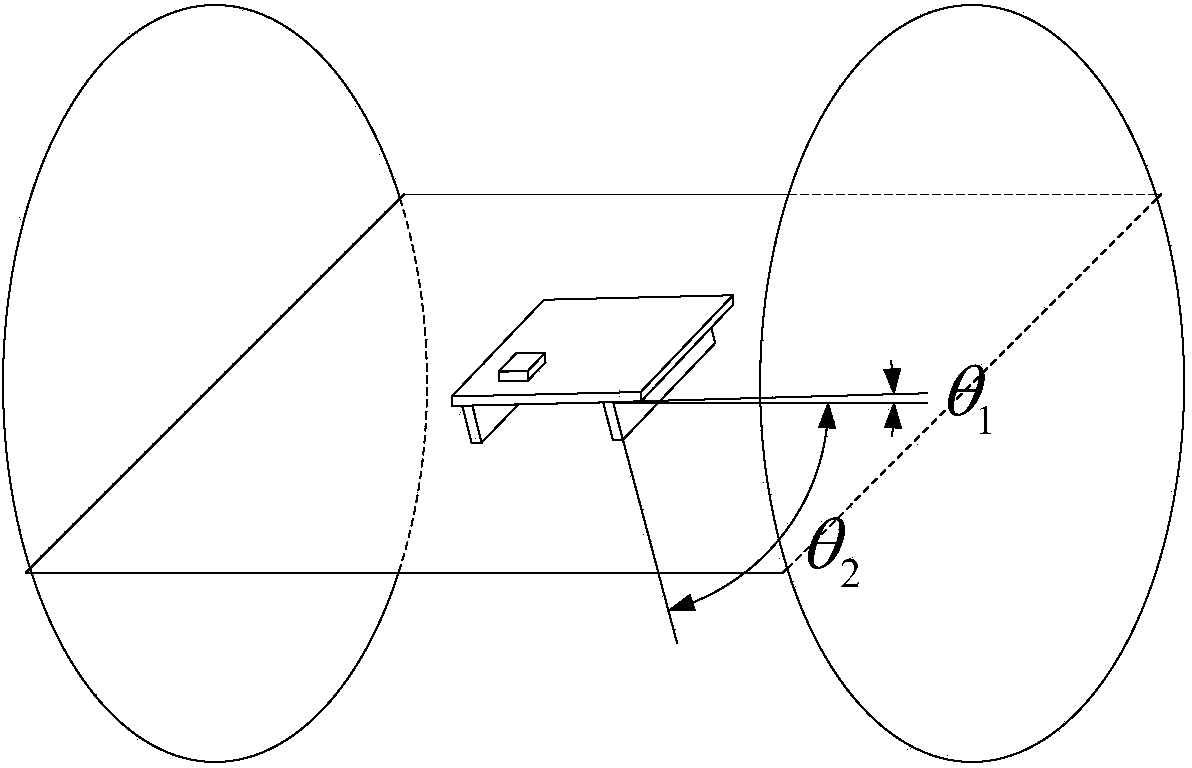
[0018] Such as Figure 5 As shown, it is a schematic diagram of the placement method of the body of the self-balancing two-wheeled vehicle on the horizontal turntable in the preferred embodiment of the method for correcting the installation offset of the attitude sensor of the present invention. In this preferred embodiment, first the installation platform of the self-balancing two-wheeled vehicle equipped with the attitude sensor is fixedly placed on the horizontal turntable 6, and then the horizontal turntable is controlled to keep rotating at a constant speed, and the installation platform and the horizontal turntable 6 are kept between the installation platform and the horizontal turntable 6. relativel...


PUM


Abstract

The invention provides an attitude sensor mounting offset correction method. The method comprises the following offset angle measurement process: fixedly arranging a mounting platform on which an attitude sensor is mounted on a horizontal rotary platform, controlling the horizontal rotary platform to rotate at a constant speed, and keeping the mounting platform and the horizontal rotary platform relative rest; acquiring pitch angular velocity omegaX0 and yaw angular velocity omegaZ0 outputted by a gyroscope in the attitude sensor when the horizontal rotary platform rotates at a constant speed; and calculating the included angle theta between the pitch axis of the gyroscope and the pitch axis of the mounting platform according to a formula theta=arctan(-omegaX0 / omegaZ0), and storing the included angle theta as the offset angle. The method also comprises a step of correcting the angular velocity outputted by the gyroscope according to the offset angle. The attitude sensor mounting offset correction method provided by the invention has the advantages of low cost, high precision and reliability, can effectively correct mounting offset of the attitude sensor, and solves the problems caused by attitude sensor mounting offset in the prior art.

Description

technical field [0001] The invention relates to a method for correcting the installation offset of an attitude sensor, in particular to a method for correcting the installation offset of an attitude sensor loaded on a self-balancing two-wheeled vehicle. Background technique [0002] Attitude sensors are widely used in various product devices that require low-cost and high-dynamic measurement of three-dimensional attitude, such as self-balancing two-wheeled vehicles, to detect motion information such as three-axis angular velocity and angle of two-wheeled vehicles. [0003] Such as figure 1 Shown is a schematic structural diagram of the attitude sensor loaded on the self-balancing two-wheeled vehicle. The attitude sensor includes a base plate 1 and a signal plate 3 arranged on the back of the base plate 1, and also includes an inclinometer 2 mounted on the base plate 1 for measuring angle information and a three-axis gyroscope mounted on the signal plate 3 for measuring angu...

Claims


Application Information

Patent Timeline
IPC IPC(8): G01C21/00
CPCG01C25/00G01C21/00
Inventor 李玺华方继勇陈养彬
Owner SHANGHAI NEW CENTURY ROBOT
Features
  • Generate Ideas
  • Intellectual Property
  • Life Sciences
  • Materials
  • Tech Scout
  • Unparalleled Data Quality
  • Higher Quality Content
  • 60% Fewer Hallucinations
Learn More