Sheet metal drawing device for electronic universal testing machine

A universal testing machine and electronic technology, which is applied in the direction of measuring device, applying stable tension/pressure to test the strength of materials, analyzing materials, etc., can solve the problems such as difficult removal of deep-drawing parts and difficult control of blank-holding force, and save molds The effect of material cost, reduced test cycle, and quick disassembly and assembly of molds

Active Publication Date: 2016-01-13
HARBIN INST OF TECH
View PDF2 Cites 0 Cited by
  • Summary
  • Abstract
  • Description
  • Claims
  • Application Information

AI Technical Summary

Problems solved by technology

[0003] The present invention provides a plate deep drawing device for an electronic universal testing machine to solve the problems that the blank holder force is difficult to control and the drawn parts are difficult to take out in the existing deep drawing process.

Method used


Image

  • Sheet metal drawing device for electronic universal testing machine
  • Sheet metal drawing device for electronic universal testing machine
  • Sheet metal drawing device for electronic universal testing machine

Examples


specific Embodiment approach 1

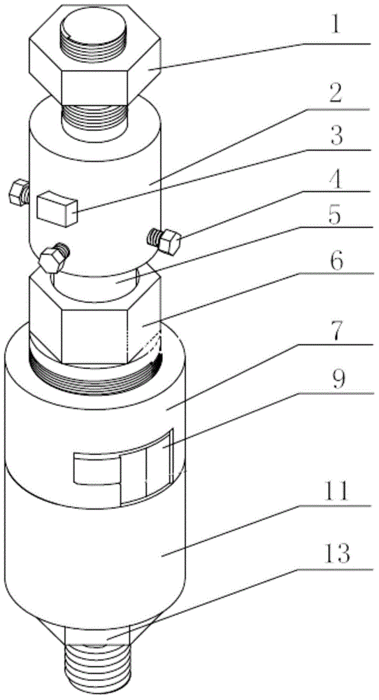
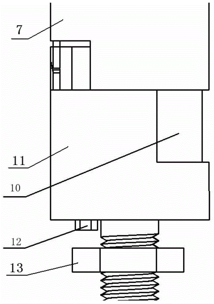
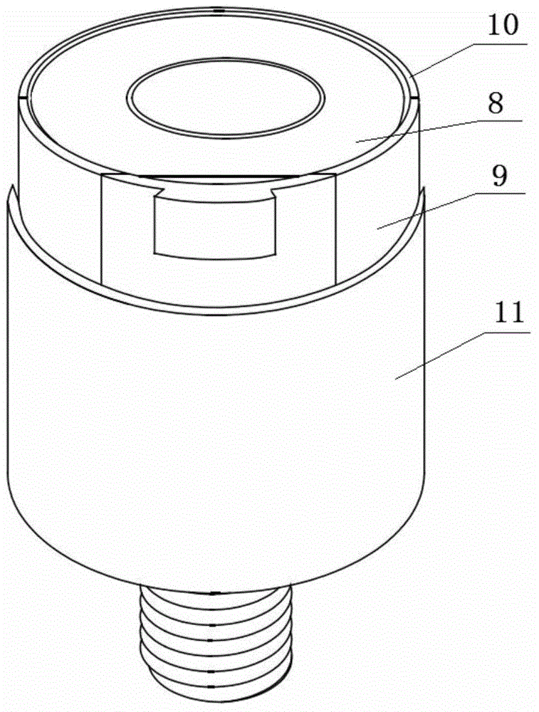
[0026] Specific implementation mode one: combine Figure 1 to Figure 13 Describe the implementation mode. This embodiment includes the back tightening nut 1 of the punch seat, the punch seat 2, the positioning pin of the punch 3, the punch 5, the blank holder nut 6, the blank holder lock 7, the blank holder ring 8, the split type Fixed semi-die 9, split-type dynamic semi-die 10, die base 11, die base back tightening nut 13, two die positioning bolts 12 and four punch positioning bolts 4, the punch base 2 consists of The bolt 2-1 is composed of the upper drum 2-2, the bottom of the upper drum 2-2 is located above, and the upper bolt 2-1 is vertically arranged on the upper end of the upper drum 2-2 along the axis of the upper drum 2-2 , the side wall of the upper drum 2-2 is provided with a first positioning through hole 2-3 which is perpendicular to the axis and passes through the axis, and the side wall of the upper drum 2-2 is evenly arranged with four threaded holes 2 along ...

specific Embodiment approach 2

[0027] Specific implementation mode two: combination Figure 5 , Figure 8 and Figure 9 To describe the embodiment, the difference between the inner diameter of the cylinder A and the outer diameter of the punch 5 in this embodiment is the thickness of one blank 14 to be drawn. Other components and connections are the same as those in the first embodiment.

specific Embodiment approach 3

[0028] Specific implementation mode three: combination Figure 4 The embodiment will be described. In this embodiment, the upper bolt 2-1 and the upper drum 2-2 are integrally formed. Other compositions and connections are the same as those in Embodiment 1 or 2.


PUM


Abstract

The invention relates to a plate deep-drawing device for an electronic universal testing machine so as to solve the problems that an edge pressing force is not easily controlled and a deep-drawn part is not easily taken out in an existing deep-drawing process. A male die is mounted in a male die holder by a male die positioning pin and is positioned and fastened by male die positioning bolts; a female die adopts a split design; two inner screw holes are formed in the bottom end of a split fixed half female die; threaded through holes are formed in a female die holder in the thickness direction; the split fixed half female die is fixed to the female die holder by female die positioning bolts; a split movable half female die is aligned to the split fixed half female die and is locked by an edge pressing buckle; an inner thread is arranged on the inner wall of the edge pressing buckle; the edge of a plate can be pressed by screwing an edge pressing coil into the inner thread of the inner wall of the edge pressing buckle; the edge pressing force can be adjusted according to the screw-in depth of the edge pressing coil; when a deep-drawing coefficient is changed, only the two half female dies and the male die need to be replaced. The plate deep-drawing device is used for a deep-drawing test and measurement of a plate limit deep-drawing coefficient.

Description

technical field [0001] The invention relates to a sheet metal deep drawing device, in particular to a metal sheet deep drawing device using an electronic universal testing machine. Background technique [0002] The deep drawing process is widely used in the field of sheet metal forming, and the deep drawing experiment can also reflect the forming ability of the sheet metal very well. During the deep drawing process, a certain blank-holding force needs to be applied to the sheet to control the directional flow of the sheet and eliminate defects such as wrinkles and cracks. The conventional method of applying blank-holder force includes applying rigid pressure by a double-action press. Although this method ensures constant blank-holder force to a certain extent, the stability is poor and the structure is complicated. The blank-holding force provided by the spring and rubber will change with the increase of the drawing displacement, and it is difficult to ensure a constant bla...

Claims


Application Information

Patent Timeline
Patent Type & Authority Patents(China)
IPC IPC(8): G01N3/02G01N3/08
Inventor 宗影影邵斌刘坡温道胜单德彬
Owner HARBIN INST OF TECH
Why Eureka
Try Eureka