Riveting machine

A riveting machine, progressive technology, applied in metal processing equipment, forming tools, manufacturing tools, etc., can solve the problems of low processing efficiency, poor quality of circuit boards, difficult to take out, etc., to achieve not easy to crack and deform, and the process of taking out the workpiece is fast Effect

Inactive Publication Date: 2013-10-02
SIMON ELECTRIC CHINA
View PDF8 Cites 12 Cited by
  • Summary
  • Abstract
  • Description
  • Claims
  • Application Information

AI Technical Summary

Problems solved by technology

The quality of the circuit board knocked by hand is poor, and the processing efficiency is low. The circuit board processed by a small punch machine has a short pressing time for the terminal post due to the characteristics of the punch machine. The greater the number of terminals, the more serious the cracking tendency of the workpiece, and the more difficult it is to remove the workpiece

Method used


Image

  • Riveting machine
  • Riveting machine
  • Riveting machine

Examples


Embodiment Construction

[0047] In order to understand the technical content of the present invention more clearly, the following examples are given in detail.

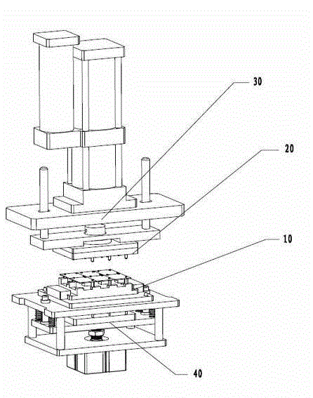
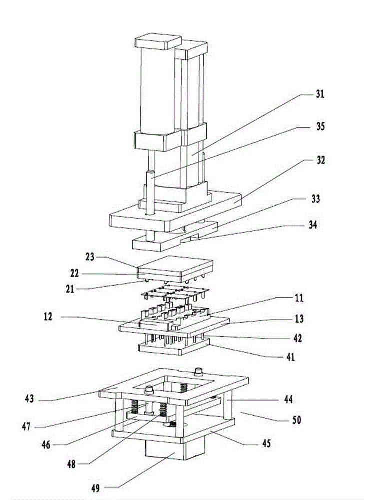
[0048] see figure 1 , which is a structural schematic diagram of the present invention, the riveting machine includes a progressive pressure unit 30 , an upper die unit 20 , a lower die unit 10 and a jacking unit 40 . The upper mold unit 20 is arranged at a corresponding position below the progressive pressure unit 30, and provides power for the upper mold unit 20, so that the upper mold unit 20 performs progressive riveting of fast forwarding, riveting and holding pressure. The moving parts in the progressive pressure unit 30 are fixedly connected to the upper mold unit 20, the lower mold unit 10 is arranged at a corresponding position below the upper mold unit 20, and the ejector unit 40 is arranged at a corresponding position below the lower mold unit 10. Location. After the workpiece is riveted, the ejector unit 40 automatically ejects ...


PUM


Abstract

The invention relates to a riveting machine. The riveting machine comprises a progressive pressure unit, wherein an upper die unit is arranged on a corresponding position below the progressive pressure unit, a movable part in the progressive pressure unit is fixedly connected with the upper die unit, a lower die unit is arranged on a corresponding position below the upper die unit, a jacking unit is arranged on the corresponding position below the lower die unit, the progressive pressure unit comprises a gas-liquid supercharging cylinder, the upper die unit comprises a plurality of forming heads, the upper die unit also comprises a forming head fixing plate, the forming heads are fixedly arranged on the lower surface of the forming head fixing plate, the lower die unit comprises a lower die, the lower die unit also comprises a lower die liner plate and a limiting block, the limiting block is fixedly arranged on the surface of the lower die liner plate, the jacking unit comprises an air cylinder and a discharging ejector pin liner plate, and the discharging ejector pin liner plate is arranged above a piston of the air cylinder. By adopting the structure, the riveting can be automatically carried out, the production efficiency is high, the workpiece after being machined is unlikely to fracture, and the workpiece after being riveted can be automatically ejected from the riveting machine.

Description

technical field [0001] The invention relates to the technical field of mechanical processing equipment, in particular to a riveting machine. Background technique [0002] In the low-voltage electrical industry, the pressure riveting method is the most common connection method between the circuit board and the terminal, but the traditional riveting method is to place multiple terminals in the limit fixture, and then manually knock or use a small punch for riveting. The quality of the circuit board knocked by hand is poor, and the processing efficiency is low. The circuit board processed by a small punch machine has a short pressing time for the terminal post due to the characteristics of the punch machine. The more the number of terminals, the more serious the cracking tendency of the workpiece, and the more difficult it is to remove the workpiece. Contents of the invention [0003] The purpose of the present invention is to overcome the above-mentioned shortcomings in the...

Claims


Application Information

Patent Timeline
Patent Type & Authority Applications(China)
IPC IPC(8): B21D39/00B21D37/10B21D37/12B21D45/02
Inventor 崔伯林
Owner SIMON ELECTRIC CHINA
Why Eureka
Try Eureka