
Fluid structure interaction coal rock shear-seepage test device

A technology of fluid-solid coupling and test equipment, which is applied in the field of test systems, can solve problems such as difficult to reflect real working conditions, accuracy cannot be guaranteed, and inconvenient operation, etc., and achieve the effect of facilitating data collection and accurate calculation, and improving test accuracy

Active Publication Date: 2014-04-23
CHONGQING UNIV
View PDF5 Cites 30 Cited by
  • Summary
  • Abstract
  • Description
  • Claims
  • Application Information

AI Technical Summary

Problems solved by technology

However, the existing test systems have the following problems: 1. Most of the applied stress loading systems are manual, so the stress loading process cannot maintain a uniform speed, and its accuracy cannot be guaranteed. In addition, loading forms such as cyclic loading cannot be realized; 2. During the shearing process, the lateral water-repelling sheet will undergo a large deformation, which will inevitably offset part of the test force, and for the silicone material with a fixed composition, there is an error; 3. The seepage enters the air from one side of the test piece Or water enters and flows out from the other side, so it is difficult to reflect the real working conditions; 4. The pressure of the gas or water passing into the shear box of the specimen is small, and it is difficult to reflect the real working conditions; 5. The installation process of each device is basically It is carried by hand, which is inconvenient to operate

Method used


Image

  • Fluid structure interaction coal rock shear-seepage test device
  • Fluid structure interaction coal rock shear-seepage test device
  • Fluid structure interaction coal rock shear-seepage test device

Examples


Embodiment Construction

[0033] Below in conjunction with accompanying drawing and embodiment the present invention will be further described:

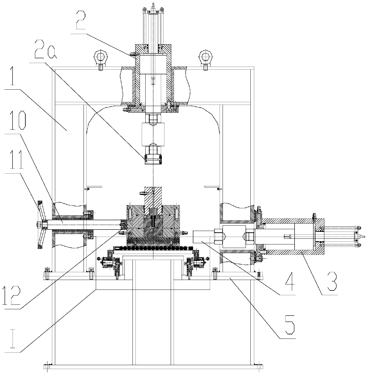
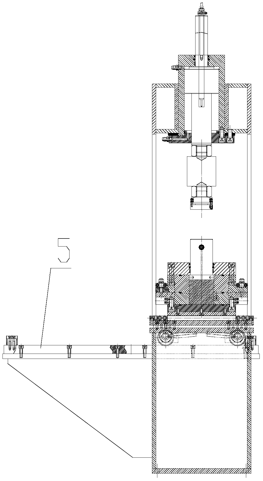
[0034] Such as Figure 1 to Figure 7 As shown, a fluid-solid coupling coal-rock shear-seepage test device includes a loading device and a shear box. The loading device comprises a frame 1, a vertical hydraulic cylinder 2 is arranged on the top of the frame 1, a vertical pressure head 2a is arranged on the vertical hydraulic cylinder 2, a horizontal hydraulic cylinder 3 is arranged on one side of the frame 1, and a horizontal hydraulic cylinder 3 A horizontal pressure head 4 is arranged on it.

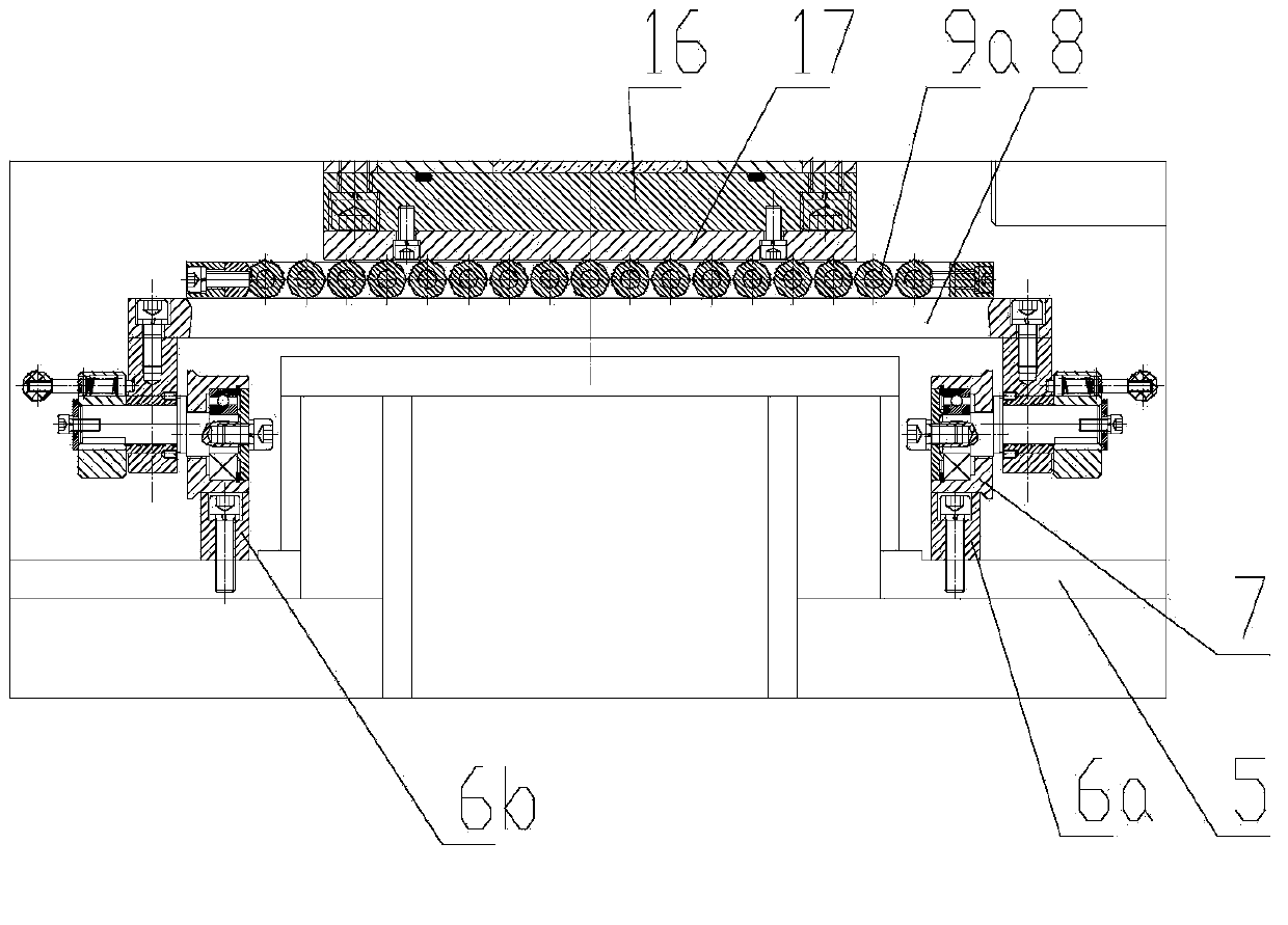
[0035] The middle part of the frame 1 is fixed with a track mounting frame 5, and the left and right sides of the track mounting frame 5 are respectively fixed with a first guide rail 6a and a second guide rail 6b, and four rollers are fitted on the first guide rail 6a and the second guide rail 6b respectively. 7. Each roller 7 is connected to the moving seat 8, and ...


PUM


Abstract

The invention discloses a fluid structure interaction coal rock shear-seepage test device which comprises a loading device and a shear box, wherein the loading device comprises a rack; a vertical hydraulic cylinder is arranged at the upper part of the rack; a horizontal hydraulic cylinder is arranged on one side of the rack; the shear box comprises an upper box body and a lower box body which are fixedly connected with each other; the upper box body and the lower box body are provided with a cavity for accommodating a test piece; the upper box body is fixedly connected with an upper cover; the lower box body is fixedly connected with a lower cover; the lower cover is fixedly connected with a base plate; the upper cover is internally matched with a pressure bar; the end part, close to the test piece, of the pressure bar is connected with a test piece pressure head by screw threads; the end part, close to the test piece, of the test piece pressure head is matched with a test piece joint by screw threads; a first sealing ring is arranged on the end face, facing towards the upper box body, of the lower box body; and the lower box body is provided with a fluid circuit on the inner side of the first sealing ring, and is provided with a second fluid joint and a third fluid joint which are communicated with the fluid circuit on the left side and the right side respectively. The test device can simulate the practical operating condition more actually, and can improve the test accuracy.

Description

technical field [0001] The invention relates to a test system, in particular to a system for testing coal and rock shear seepage tests. Background technique [0002] During the production process of the mine, the excavation engineering destroys the balance of the stress field of the original rock and the balance of the original gas pressure, forming the stress redistribution and gas flow of the surrounding rock mass. Coal bed gas (coal bed methane) permeability is a physical parameter that reflects the difficulty of gas seepage in coal seams, and is also an important parameter for gas seepage mechanics and engineering. Therefore, the research on the calculation method of coal seam gas permeability or coal seam air permeability coefficient is the key technology for the development of gas seepage mechanics, and it is also the key starting point for coal mine safety workers to study a series of mine safety issues such as coal and gas outburst and gas explosion. [0003] The de...

Claims


Application Information

Patent Timeline
IPC IPC(8): G01N3/24G01N15/08
Inventor 许江尹光志王维忠彭守建李波波蒋长宝刘东刘义鑫叶桂兵程立朝
Owner CHONGQING UNIV
Features
  • Generate Ideas
  • Intellectual Property
  • Life Sciences
  • Materials
  • Tech Scout
  • Unparalleled Data Quality
  • Higher Quality Content
  • 60% Fewer Hallucinations
Learn More