Far field distributed parallel sub-array wave beam formation method

A distributed, sub-array technology, used in radio wave measurement systems, radio wave reflection/re-radiation, utilization of re-radiation, etc., to reduce memory requirements, save parameter storage space, and meet real-time requirements.

Active Publication Date: 2014-04-23
ZHEJIANG UNIV
View PDF3 Cites 7 Cited by
  • Summary
  • Abstract
  • Description
  • Claims
  • Application Information

AI Technical Summary

Problems solved by technology

The latter requires less computing requirements than the former, but

Method used


Image

  • Far field distributed parallel sub-array wave beam formation method
  • Far field distributed parallel sub-array wave beam formation method
  • Far field distributed parallel sub-array wave beam formation method

Examples


Embodiment Construction

[0030] In order to describe the present invention more specifically, the far-field distributed parallel sub-array beamforming algorithm of the present invention will be described in detail below with reference to the drawings and specific implementation methods.

[0031] A far-field distributed parallel subarray beamforming method, comprising the following steps:

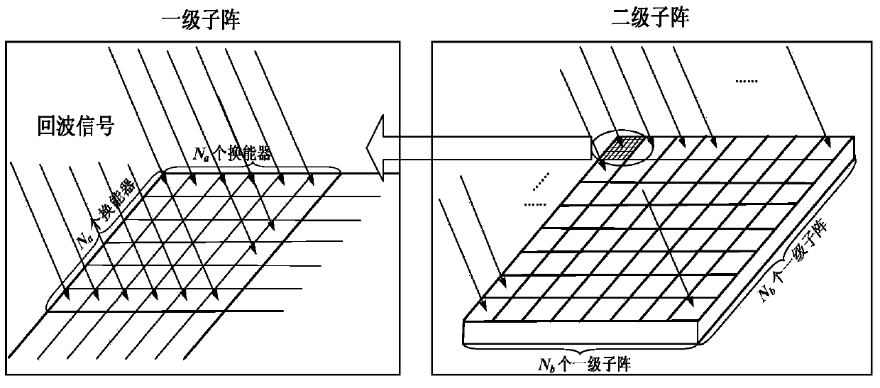
[0032] (1) if figure 1 As shown, the full transducer array is divided into several first-level sub-arrays, each first-level sub-array is used as a basic unit, and all first-level sub-arrays form a second-level sub-array.

[0033] The purpose of sub-array division is to reduce the memory requirement and calculation amount of beamforming. A full array of transducers consisting of N×N transducers with a transducer spacing of d is decomposed into Nb×Nb shapes Regular and non-overlapping square sub-arrays (that is, first-level sub-arrays), each sub-array is composed of Na×Na transducers.

[0034] With each first-level ...


PUM


Abstract

The invention discloses a far field distributed parallel sub-array wave beam formation method. The method comprises the following steps: (1), dividing the full array of an energy transducer into a plurality of primary sub arrays, wherein each primary sub array is taken as a basic unit, and all the primary sub arrays form a secondary sub array; (2), performing parallel wave beam formation on all the primary sub arrays; and (3), taking the wave beam formation result of each primary sub array as a basic element of the secondary sub array, and after wave beam extraction, performing secondary sub array wave beam formation. By using the far field distributed parallel sub-array wave beam formation method provided by the invention, a wave beam directional diagram which is close to the main lobe width and the sidelobe peak value of a direct wave beam formation algorithm can be obtained under the condition that a time delay parameter storage space and a calculating load are reduced, the calculating efficiency is greatly improved, and the real-time demand for underwater three-dimensional sonar imaging is satisfied.

Description

technical field [0001] The invention relates to the field of three-dimensional sonar imaging, in particular to a far-field distributed parallel sub-array beamforming method. Background technique [0002] The role of underwater detection technology in the fields of physics, biology, geography, archaeology and industrial applications has become increasingly prominent. Real-time 3D sonar imaging technology is one of the most important innovations in the field of underwater applications in recent years. [0003] According to the imaging principle, underwater three-dimensional acoustic imaging systems include three categories: (1) holographic acoustic imaging; (2) acoustic lens imaging; (3) beamforming acoustic imaging. The detection range of the holographic acoustic imaging system is narrow; while the acoustic lens imaging system increases with the increase of the detection distance, the volume requirement of the optical prism is too large; with the rapid development of digital ...

Claims


Application Information

Patent Timeline
IPC IPC(8): G01S7/52
CPCG01S7/521G01S7/54G01S13/89
Inventor 陈耀武韩业强周凡田翔蒋荣欣
Owner ZHEJIANG UNIV
Why Eureka
Try Eureka