Protection strengthening type wing-shaped fixture

A reinforced fixture technology, which is applied in the field of wing fixtures, can solve the problems of broken pull plates on both sides, insulator strings or wires falling off, hindering the assembly and operation of live working tools, etc., and achieve the effect of increasing the stroke margin

Inactive Publication Date: 2014-04-23
STATE GRID CORP OF CHINA +2
View PDF6 Cites 6 Cited by
  • Summary
  • Abstract
  • Description
  • Claims
  • Application Information

AI Technical Summary

Problems solved by technology

Practice has proved that there are three obvious hidden defects in the wing fixture. One is that the pull plates on both sides of it may break, the other is that the fittings connecting the cross arm may be aged and broken, the third is that the stroke of the two-way screw is short and cannot be placed in place, and the fourth is that The front clamp is easy to release, and the operation of closing the door is not convenient enough, so it is easy to cause accidents of insulator strings or wire falling off
[0004] In order to prevent the above-mentioned accidents from happening, in the actual operation, the insulation protection rope is generally used as a backup protection measure to replace the linear insulator string with electricity. However, using the protection rope as a backup protection measure for replacing the tension insulator string increases the safety. , but it brings inconvenience to the operation, and it is difficult to bind firmly with the protection of the cross arm
If the protection rope is tightened, it will hinder the assembly and operation of live working tools; if the protection rope is loosened, it will be difficult to withstand the impact force when the tension wire falls off
In actual work, there are still some operators who discard the protective rope and lose the second protective measures. Although the wing clamps are still in use, the above problems are worrying.

Method used


Image

  • Protection strengthening type wing-shaped fixture
  • Protection strengthening type wing-shaped fixture

Examples


Embodiment 1

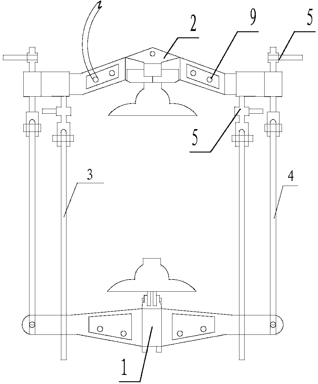
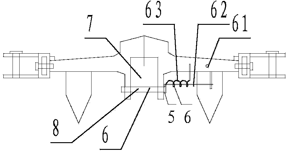
[0024] A protection-reinforced wing-shaped fixture, including a front clamp 1, a rear clamp 2, insulating pull plates 3 on both sides, and an insulating protection rope 4, and two sides of the front clamp and the rear clamp are provided with parallel to the insulation pull The protective insulation protection rope of the board and the tightening screw rod 5, one end of the insulating protection rope is arranged on the front card, and the other end is connected with the tightening screw rod, and the tightening screw rod is connected on the rear card, and the wire of the tightening screw rod The rod length is greater than the screw length of the tight-wire screw used to fix the insulating stay plate. Also be provided with card slot door sealing device 6 on the front clamping fixture, described card slot door sealing device 6 includes bayonet pin 61 frame and spring guide rod 62, described bayonet pin frame and spring guide rod are arranged on for card slot. Enter one side of the...


PUM


Abstract

The invention discloses a protection strengthening type wing-shaped fixture comprising a front clamp, a rear clamp, insulation pull plates on the two sides and protection ropes, wherein the protective insulation protection ropes parallel to the insulation pull plates and wire tightening screws are arranged on the two sides of the front clamp and the rear clamp of the fixture, one ends of the insulation protection ropes are arranged on the front clamp, the other ends are connected with the wire tightening screws, the wire tightening screws are connected to the rear clamp, and the screw length of the wire tightening screws is greater than that of wire tightening screws used for fixing the insulation pull plates. As the protection ropes parallel to the insulation pull plates are arranged on the two sides of the front clamp and the rear clamp of the fixture, a protection plate on the same side can still be stressed to play an effective protection role when one pull plate or pin is broken. Therefore, the occurrence of insulator string or wire falling-off accidents caused by pull plate fracture or tripping can be avoided.

Description

technical field [0001] The invention relates to a wing clamp, in particular to a protection-reinforced wing clamp. [0002] Background technique [0003] During the live operation of I10kV-220kV lines, wing-shaped clamps are usually used to replace the single string insulators of tension towers. Practice has proved that there are three obvious hidden defects in the wing fixture. One is that the pull plates on both sides of it may break, the other is that the fittings connecting the cross arm may be aged and broken, the third is that the stroke of the two-way screw is short and cannot be placed in place, and the fourth is that The front clamp is easy to release, and the operation of sealing the door is not convenient enough, so it is easy to cause accidents of insulator strings or wire falling off. [0004] In order to prevent the above-mentioned accidents from happening, in the actual operation, the insulation protection rope is generally used as a backup pr...

Claims


Application Information

Patent Timeline
Patent Type & Authority Applications(China)
IPC IPC(8): H02G1/02
Inventor 黄玉林
Owner STATE GRID CORP OF CHINA
Why Eureka
Try Eureka