
Bubble generating mechanism and showerhead with bubble generating mechanism

A technology for generating bubbles and components, which is applied in mixers, injection devices, sanitary equipment, etc., and can solve problems such as increased fluid resistance, insufficient bubble precipitation, and insufficient effects

Active Publication Date: 2014-04-23
SHIBATA OU
View PDF8 Cites 25 Cited by
  • Summary
  • Abstract
  • Description
  • Claims
  • Application Information

AI Technical Summary

Problems solved by technology

Therefore, the fluid resistance when passing through the reduced-diameter hole increases and cannot increase to the expected flow rate. In addition, the reduced-diameter hole is also easily subjected to radial backpressure from the inner wall surface of the hole, so the effect of cavitation (decompression) is not good. Sufficient, the difficulty that the amount of bubble precipitation is easily insufficient

Method used


Image

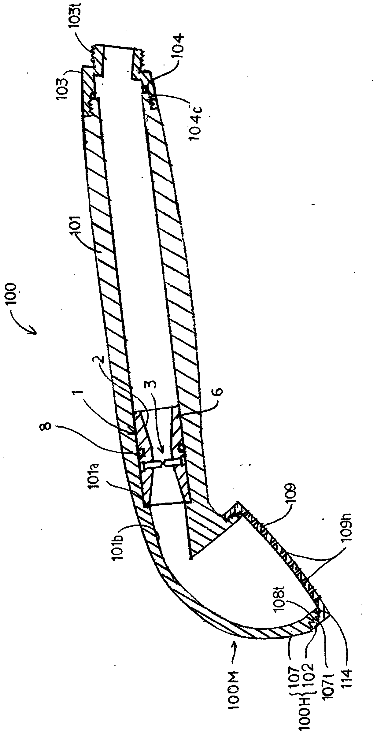
  • Bubble generating mechanism and showerhead with bubble generating mechanism
  • Bubble generating mechanism and showerhead with bubble generating mechanism
  • Bubble generating mechanism and showerhead with bubble generating mechanism

Examples


Embodiment

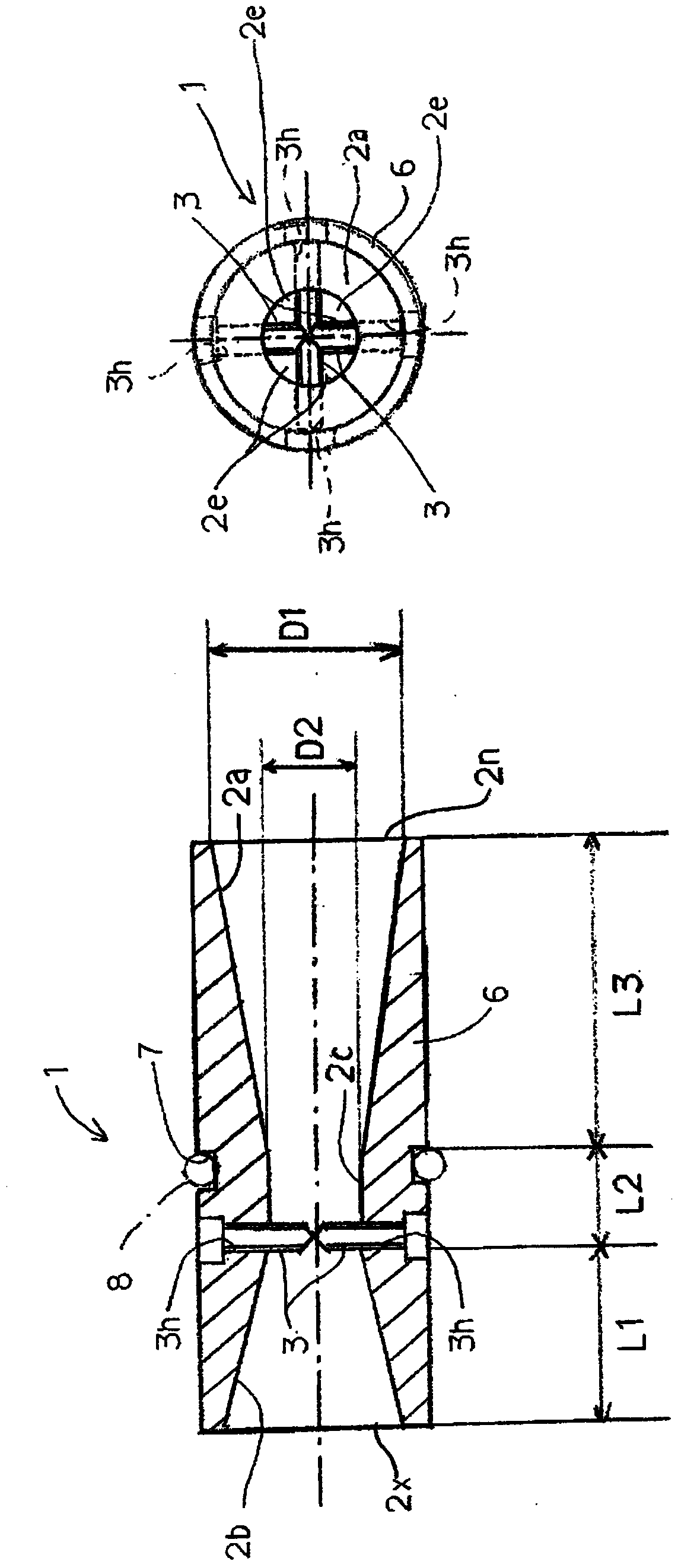
[0102] Prepare to specify in the following way figure 2 The specific size of the flow path and conflicting parts of the bubble generator 2.

[0103] ( image 3 )

[0104] ・Inflow port 2n and outflow port 2x: inner diameter = 16mm

[0105] ・Inflow side tapered part 2a: flow path length L3=24mm

[0106] ・Outflow side tapered part 2b: flow path length L1=16mm

[0107] ·Reduced diameter part 2c: inner diameter D2=8mm, flow path length L2=8mm

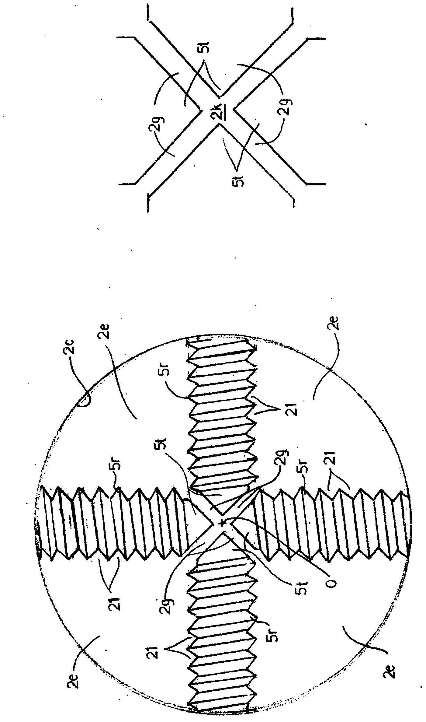
[0108] Conflict part 3: Thread outer diameter: M2, the front end is a sharp point with a front end angle of 90° after cutting a section including the axis

[0109] The size of the central gap 2k (the length between the sharp points of the opposing conflicting parts 3): three conditions of 0mm, 0.18mm and 0.36mm

[0110] A hose was connected to the bubble generator 2, water at 10° C. was supplied to the inflow port 2n at a supply pressure of 0.12 MPa, and the sprayed water was discharged into a water tank with a volume of about 90 lite...


PUM

PropertyMeasurementUnit
The average diameteraaaaaaaaaa

Abstract

Provided is a bubble generating mechanism that does not use a complicated air mixing mechanism and generates micro-bubbles in a sufficient quantity. A flow path (2) that connects an inflow opening (2n) that opens on an inflow end and an outflow opening (2x) that opens on an outflow end is formed in a state passing completely through a member main body (6), and a constricted part (2c) of which the flow-through cross-sectional area is smaller than the inflow opening (2n) is formed in a position within that flow path (2). Colliding parts (3) that further reduce the cross-sectional area of the flow path in the constricted part (2c) are disposed in the constricted part (2c) in a state that divides the axial plane of the flow path (2) into three or more segment areas (2e).

Description

technical field [0001] The present invention relates to a bubble generating mechanism, and in particular to a mechanism suitable for generating fine bubbles such as microbubbles and nanobubbles, and a spray head using the bubble generating mechanism. Background technique [0002] Bubbles formed in water are classified into millimeter bubbles or microbubbles (more specifically, micro / nanobubbles, nanobubbles, etc.) according to their sizes. Millimeter bubbles are somewhat gigantic air bubbles that rise rapidly through the water before eventually bursting and disappearing at the surface. On the other hand, air bubbles with a diameter of 50 μm or less have special properties such that they stay in water for a long time due to their fineness, shrink further in water due to their excellent gas dissolving power, and then disappear (completely dissolve) in water. Bubbles with a diameter of 50 μm or less are called microbubbles (Non-Patent Document 1). In this specification, "micr...

Claims


Application Information

Patent Timeline
IPC IPC(8): B01F5/06A47K3/28B01F3/04B01F5/00
CPCB01F3/04503B01F5/0671B05B1/185B01F5/0663B01F5/068B01F2003/04858B05B1/18B01F23/2323B01F25/44163B01F25/4412B01F25/4422B01F23/2375
Inventor 加藤启雄柴田芳树
Owner SHIBATA OU
Learn More