A solar-assisted carbon dioxide capture integrated system

A carbon dioxide, integrated system technology, applied in solar thermal power generation, solar thermal devices, inorganic chemistry and other directions, can solve the problems of high energy consumption, reduce the efficiency of power plants, etc., to maintain stable operation, reduce adverse effects, and improve the overall efficiency of the system. Effect

Active Publication Date: 2015-12-02
TIANJIN UNIV
View PDF5 Cites 1 Cited by
  • Summary
  • Abstract
  • Description
  • Claims
  • Application Information

AI Technical Summary

Problems solved by technology

[0005] Aiming at the high energy consumption problem caused by the current capture system, the present invention proposes a solar-assisted carbon dioxide capture integrated system, which can make full use of medium and low temperature solar heat collection to compensate the energy consumption of the traditional capture system according to different integration connection relationships demand, while realizing cascade utilization of solar energy, it can effectively reduce the efficiency drop caused by steam extraction in power plants

Method used


Image

  • A solar-assisted carbon dioxide capture integrated system
  • A solar-assisted carbon dioxide capture integrated system

Examples


Embodiment 1

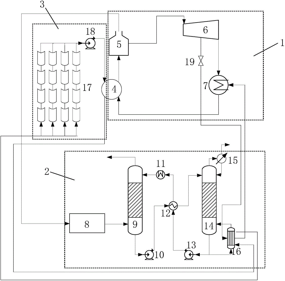
[0024] When the heat collection temperature of the solar heat collection subsystem 3 is medium temperature, its connection relationship is: as figure 1 As shown, the outlet end of the working medium in the solar thermal collection subsystem 3 is connected to the high-temperature side inlet of the feedwater heat exchanger 4 in the power generation subsystem 1, and medium-high temperature solar thermal collection heating is used to replace the extraction type feedwater heating, The high temperature side outlet of the feed water heat exchanger 4 is connected with the high temperature side inlet of the reboiler 16 in the carbon dioxide capture system 2, and the high temperature side outlet of the reboiler 16 is connected with the solar heat collection subsystem 3 of the working fluid inlet port connected to form a solar heat collection cycle. The connection method in Example 1 can collect heat from the solar heat collection subsystem to a medium-high temperature of about 200-350°C...

Embodiment 2

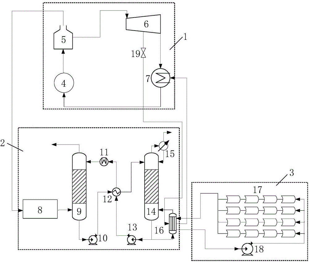
[0026]The outlet end of the working fluid of the solar heat collection subsystem 3 is connected to the high temperature side inlet port of the reboiler 16 in the carbon dioxide capture subsystem 2, and the high temperature side outlet of the reboiler 16 is connected to the solar collector The working fluid inlets of the thermal subsystem 3 are connected to form a solar heat collection cycle. The connection method of embodiment 2 can directly use the solar heat collection subsystem to collect heat from the working medium fluid in the solar heat collector series to the temperature range required by the reboiler and supply it to the reboiler, which can make full use of the system while simplifying the system. It improves the high heat collection efficiency of the solar heat collection system at low temperature, and reduces the heat dissipation loss of the working medium fluid at high temperature.

[0027] To sum up, by adopting different connection methods for the heat output end...


PUM


Abstract

The invention discloses a solar aided carbon dioxide trapping integrated system, which mainly comprises three parts, i.e. a power generation subsystem, a carbon dioxide trapping subsystem and a solar heat collection subsystem, wherein the subsystems are connected mainly through a boiler feed water heater, a reboiler and a flue gas pretreatment device to form the whole integrated system. According to the system, the high and low energy requirements of related parts among the solar heat collection subsystem, the power generation subsystem and the carbon dioxide trapping subsystem are reasonably allocated and integrated in different connecting ways at the heat output end of the solar heat collection subsystem to realize the gradient utilization of energy, so that the energy consumption of extraction of vapor from a steam turbine of a power plant can be greatly reduced, the stability of the power plant can be maintained, the dual effects of utilizing renewable energy resources and reducing the carbon dioxide emission of the power plant are achieved, and the large-scale application of solar energy and an integrated flue gas trapping technology in China are forcefully promoted.

Description

technical field [0001] The invention relates to a medium and low temperature solar energy assisted carbon dioxide capture integration technology, specifically relates to the integration of a medium and low temperature solar heat collection system and a carbon dioxide capture system in flue gas, using solar energy to provide energy compensation for the carbon dioxide capture system, and realizing cascaded utilization of solar energy At the same time, it effectively reduces the efficiency drop of the power plant due to steam extraction. Background technique [0002] In the current chemical absorption capture system, a large amount of power plant steam is consumed during solution regeneration, which causes a decrease in power plant efficiency and increases capture costs, becoming a constraint for CO 2 The main factor for the large-scale application of capture technology. [0003] For the CO in the flue gas of the existing power plant 2 The technical solution of post-combustio...

Claims


Application Information

Patent Timeline
Patent Type & Authority Patents(China)
IPC IPC(8): B01D53/18C01B31/20F24J2/04C01B32/50
CPCY02E10/44Y02P20/121Y02P20/123Y02P20/124Y02P20/10Y02P20/133
Inventor 严晋跃王甫赵军李海龙赵力
Owner TIANJIN UNIV
Why Eureka
Try Eureka