combine harvester

A combine harvester and machine body technology, applied to harvesters, cutters, mechanical equipment, etc., can solve the problems of damage to purification devices, reduction of storage capacity of grain boxes, etc., to prevent clogging, prevent reduction in capture efficiency, and improve operating efficiency Effect

Active Publication Date: 2015-08-12
ISEKI & CO LTD
View PDF7 Cites 0 Cited by
  • Summary
  • Abstract
  • Description
  • Claims
  • Application Information

AI Technical Summary

Problems solved by technology

[0005] The combines described in Patent Documents 1 and 2 utilize steel pipes to connect the exhaust manifold of the engine and the purifying device for purifying unburned fuel and granulated substances. There is a problem that the purification device is damaged in advance due to the vibration of the engine
In addition, since the cleaning device is arranged between the side wall of the threshing device and the side wall of the grain tank, it is necessary to narrow the width of the grain tank in the left-right direction, and there is a problem that the storage capacity of the grain tank decreases.

Method used


Image

  • combine harvester
  • combine harvester
  • combine harvester

Examples


no. 2 approach

[0132] Below, refer to Figure 13 ~ Figure 17 A second embodiment of the present invention will be described in detail. In addition, the same code|symbol is attached|subjected to the same component, and description is abbreviate|omitted.

[0133] The engine 9 is attached to the frame 41 via an elastic engine mount similarly to the first embodiment.

[0134] Specifically, the engine-side support member 9A provided at the lower portion of the engine 9 is supported by the body-side support member 41A via an elastic engine mount 9B.

[0135] The DPF unit 40 is supported by a frame 102 made of steel and provided on the frame 41 . The frame 102 is composed of a front frame 103 , a rear frame 104 , an upper connection frame 105 , a lower connection frame 106 , a cover 107 , and a lower support member 108 and an upper support member 109 for supporting the DPF unit 40 .

[0136] In addition, the base 41 is provided with a pitch cylinder 57 fixed to a rear connecting plate 56 whose b...

no. 3 approach

[0171] Next, a third embodiment of the present invention will be described in detail with reference to the drawings. In addition, the same code|symbol is attached|subjected to the same component, and description is abbreviate|omitted.

[0172] Such as Figure 18 As shown, in order to remove impurities contained in the exhaust gas discharged from the engine 9 , a DPF unit 40 is connected to the connecting pipe 70 of the engine 9 .

[0173] The DPF unit 40 of the third embodiment is supported by a frame 62 made of steel and provided on a frame 41 . The frame 62 is composed of a front frame 63 , a rear frame 64 , an upper connection frame 65 , a lower connection frame 66 , a cover 67 , and a support member 68 for supporting the DPF unit 40 from below.

[0174] Like the front frame 43 of the first embodiment, the front frame 63 is formed by a front left column and a front right column. The base of the front left column is fixed to the machine base 41 and extends upward. The bas...


PUM


Abstract

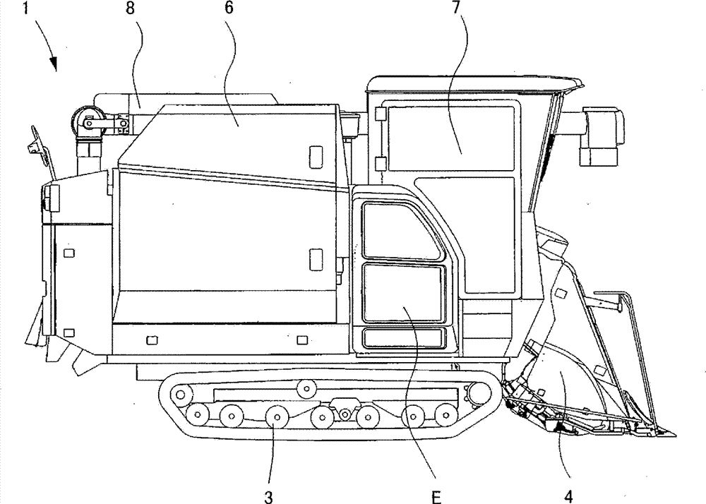
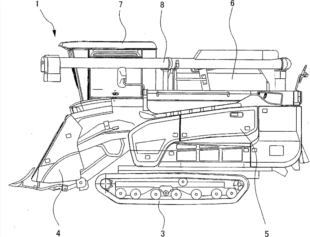
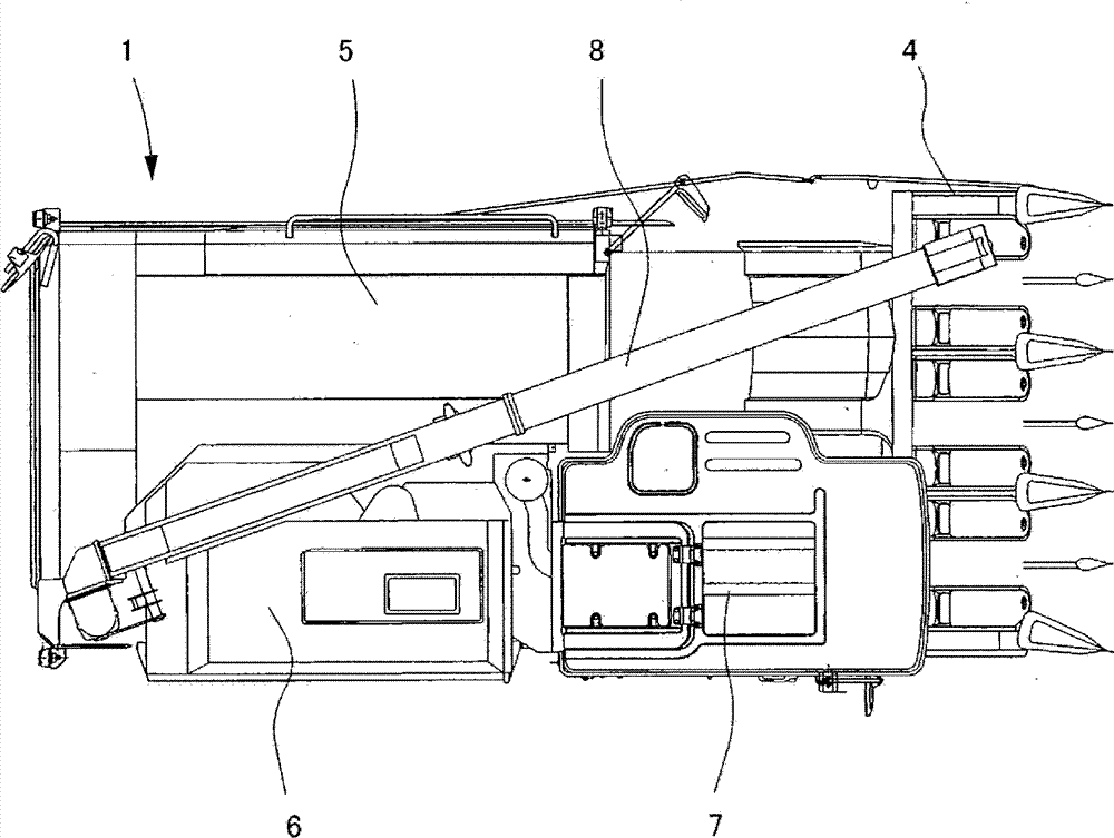
A combine harvester comprises a purification device excellent in durability and a grain tank capable of storing a great quantity of grains. A DPF (diesel particulate filter) unit (40) which is used for purifying exhaust of an engine (9) is disposed on a portion, in the bilateral center of a body, of a transverse side of a threshing device (5), and an exhaust manifold (30B) of the engine (9) is connected with a gas inlet (40E) of the DPF unit (40) through flexible connecting pipes (52 and 72). In addition, the DPF unit (40) is disposed between the threshing device (5) and the grain tank (6), the lower portion of the grain tank (6) is provided with an inclined wall (21D) inclined downward towards the outer side of the body, and the DPF unit (40) enters a space of the lower side of the inclined wall (21D).

Description

technical field [0001] The present invention relates to a combine equipped with a diesel particulate filter. Background technique [0002] Conventionally, the structure which arrange|positions the exhaust device which purifies unburned fuel and granular material contained in exhaust gas in the space formed between a threshing apparatus and a grain tank is proposed (refer patent document 1, 2). [0003] Patent Document 1: Japanese Patent Laid-Open No. 2010-84542 [0004] Patent Document 2: Japanese Patent Laid-Open No. 2010-209813 [0005] The combine harvesters described in Patent Documents 1 and 2 use steel pipes to connect the exhaust manifold of the engine and the purifying device for purifying unburned fuel and granulated substances. Therefore, there is a problem that the purifying device is damaged prematurely due to engine vibration. In addition, since the cleaning device is arranged between the side wall of the threshing device and the side wall of the grain tank, i...

Claims


Application Information

Patent Timeline
Patent Type & Authority Patents(China)
IPC IPC(8): A01D41/02
CPCA01D41/12F01N3/021F01N13/1838F01N2590/08F16L27/10
Inventor 藤田靖上村孝彦
Owner ISEKI & CO LTD
Why Eureka
Try Eureka