Mount for a boat propulsion unit

a technology for propulsion units and boats, applied in the direction of waterborne vessels, propeller elements, vessel construction, etc., can solve the problems of rigid mounting, noise, vibration, rigid mounting,

Inactive Publication Date: 2013-10-03
OCEANVOLT
View PDF1 Cites 5 Cited by
  • Summary
  • Abstract
  • Description
  • Claims
  • Application Information

AI Technical Summary

Benefits of technology

[0014]In use, the first and second mating parts may be configured to apply a force to compress the gasket when the first and second mating parts are connected. The force may be applied generally vertically through a portion of the gasket received in the recess. Thus, the force to compress the gasket may be transmitted through the innermost side of the gasket causing the gasket to expand radially outwardly into the groove to seal against the collar.
[0015]The applicants have found that the shape of the groove in the collar and the shape of the recess formed by the first and second mating parts can influence the power transfer and vibration dampening properties of the mount. Accordingly, the shapes of the groove and recess should be careful chosen to provide the desired properties.
[0016]The groove and the recess may have similar or different cross-sections.
[0017]The groove and / or the recess may be generally V-shaped or C-shaped. Thus, the groove and / or the recess may be formed by two inclined annular surfaces having an angle of less than 180 degrees there-between. The angle may be between 180 degrees and 90 degrees but is preferably 90 degrees or less. The inclined surfaces may join via a curved interface or a straight (e.g. vertical) interface. In certain embodiments, the groove and / or recess may be part-circular, for example, hemispherical.
[0018]The gasket may comprise rubber and may be in form of an O-ring. As above, the type of rubber employed in the gasket may influence the power transfer and vibration dampening properties of the mount.
[0019]The gasket may be substantially toroidal forming a circle in plan view. Alternatively, the gasket may be substantially oval, obround or elongated in plan view. The use of an oval, obround or elongated gasket may be particularly advantageous since it has been found that approximately 80% of the forces applied to the gasket in use are likely to be in the forwards and backwards directions and these can be most effectively managed by having a gasket elongated in the forwards and backwards directions.

Problems solved by technology

Such a rigid mounting is fairly easy to achieve, however, a disadvantage is that a rigid mounting will transfer any vibrations caused by the propeller directly to the structures of the boat.
This may result in noise, vibrations and, in the worst case, damage to some structures.

Method used


Image

  • Mount for a boat propulsion unit
  • Mount for a boat propulsion unit
  • Mount for a boat propulsion unit

Examples


first embodiment

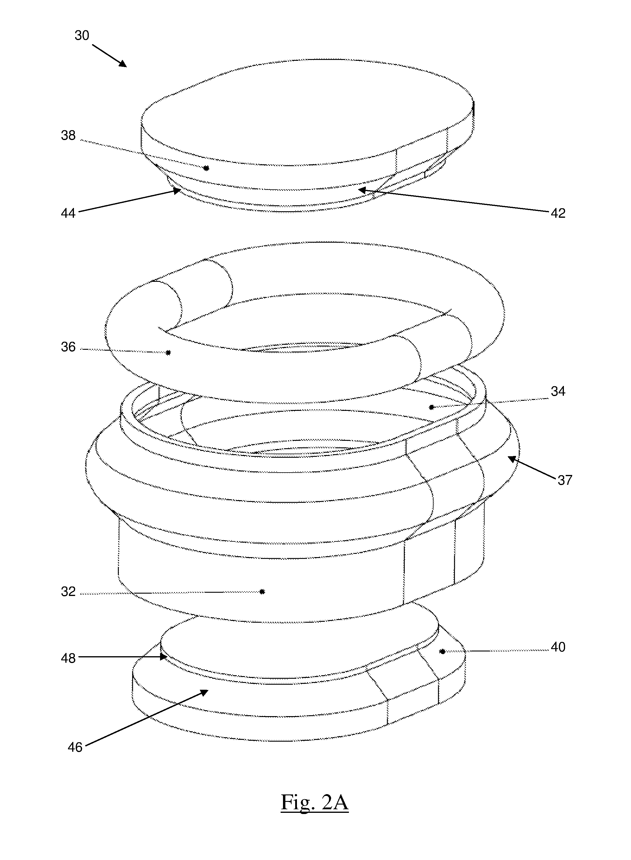
[0045]With reference to FIG. 2A, there is illustrated a mount 30 for a boat propulsion unit (not shown) according to the present invention. The mount 30 comprises a hollow generally cylindrical collar 32 (also known as a motor bed). In this embodiment, the collar 32 is designed to be integrally moulded within a hole in the bottom of a boat's hull (not shown). The collar 32 includes an inner annular groove 34 configured to partly receive an annular rubber gasket in the form of O-ring 36. In this particular embodiment, the collar 32 also includes an annular bulge 37 on its external surface, to accommodate the inner annular groove 34.

[0046]It will be noted from FIG. 2A that the mount 30 has a generally obround shape when viewed from above. As stated previously, this shape is advantageous in handling the forwards and backwards forces applied to the mount 30 when in use.

[0047]The mount 30 further comprises an upper part 38 configured for attachment to an inboard motor or its housing (not...

second embodiment

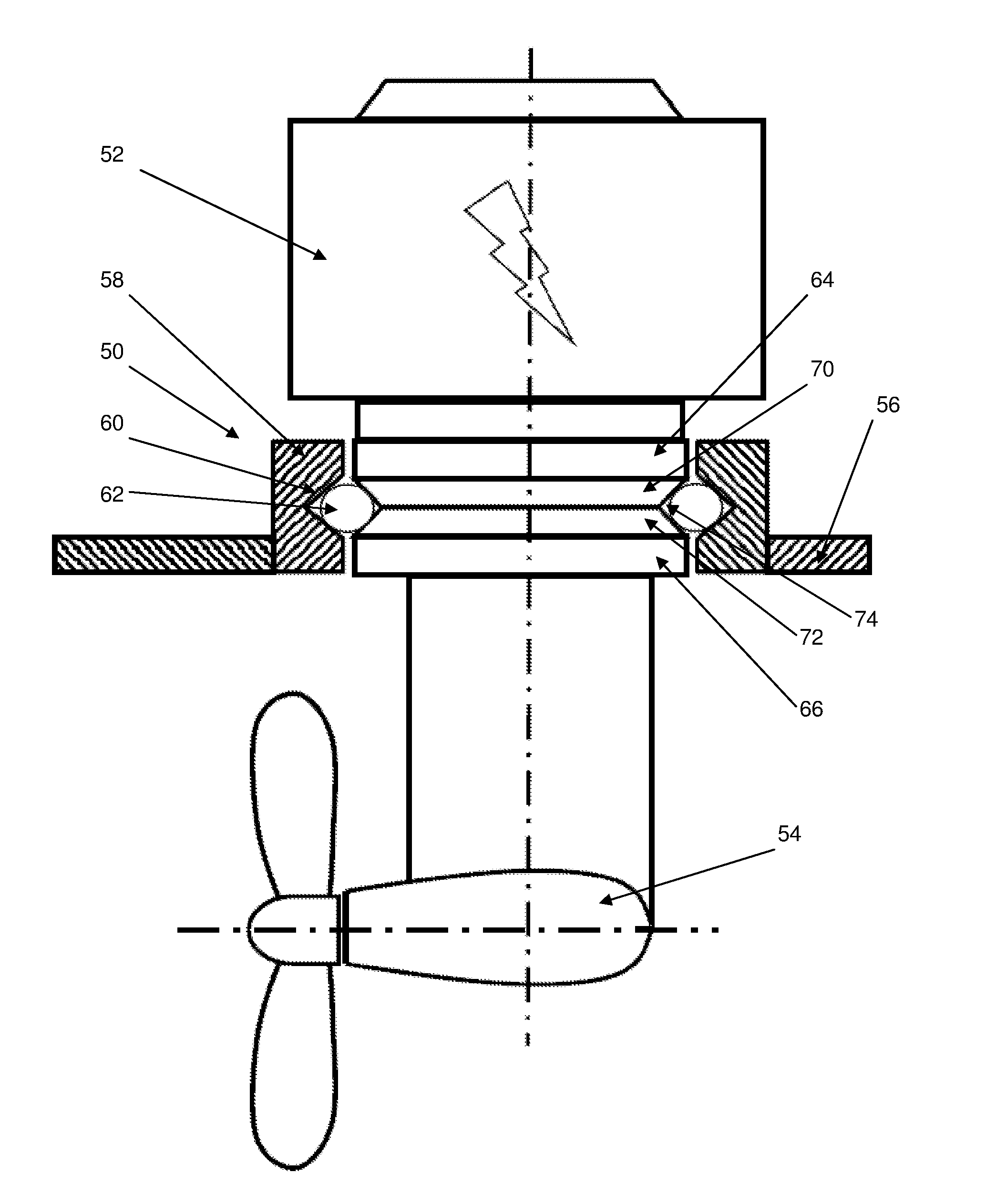
[0052]FIG. 2B shows a part cross-sectional view of an assembled mount 50, similar to that shown in FIG. 2A, when attached to a propulsion unit comprising an inboard motor 52 and saildrive 54 of a boat 56, according to the present invention. The mount 50 comprises a hollow obround cylindrical collar 58 affixed within a hole in the bottom of the boat's hull 56. The collar 58 includes an inner annular V-shaped groove 60 configured to partly receive an annular rubber gasket in the form of O-ring 62.

[0053]As above, the mount 50 further comprises an upper part 64 which, in this case, is attached to the inboard motor 52 and a lower part 66 which, in this case, is attached to the saildrive 54. Also as described above, the upper part 64 and the lower part 66 will be hollow in practice to allow a motor drive shaft (not shown) to extend through the mount 50 to operate the saildrive 54 and the upper and lower parts 64, 66 also include an attachment mechanism (not shown) which is described below...


PUM

PropertyMeasurementUnit
angleaaaaaaaaaa
angleaaaaaaaaaa
forceaaaaaaaaaa

Abstract

A mount for a boat propulsion unit comprises a collar for mounting around an aperture in a boat's hull, the collar having an annular groove on an inner surface thereof; a first mating part for mounting an inboard portion of a propulsion unit to the boat; and a second mating part, connectable to the first mating part, for mounting an outboard portion of a propulsion unit to the boat. The first and second mating parts are connectable through the collar and are configured such that when they are connected they form an external annular recess in an outer surface and an annular gasket is located partly in the groove and partly in the recess to form a seal there-between.

Description

FIELD OF THE INVENTION[0001]This invention relates to a mount for a boat propulsion unit. Particularly, but not exclusively, the invention relates to a mount for mounting an inboard propulsion unit in a boat hull.BACKGROUND TO THE INVENTION[0002]Aspects of the present invention are particularly concerned with the mounting of electric propulsion units that consist of a saildrive projecting from the bottom of a boat's hull and that have an inboard motor mounted above the saildrive. In essence, a saildrive can be considered as a sailboat's equivalent of a motorboat's sterndrive, which projects from the stern of a boat and usually has a drive mounted outside of the hull (and is therefore also known as an outdrive). A saildrive is significantly different to a traditional inboard motor since it is not connected to the motor via a standard propeller shaft. Instead, inside a saildrive casing there is normally an L-gear that consists of a vertical (pinion) shaft, a horizontal (propeller) sha...

Claims


Application Information

Patent Timeline
Patent Type & Authority Applications(United States)
IPC IPC(8): B63H21/30
CPCB63H5/07B63H21/305Y10T29/49826B63H21/30B63H2005/075
Inventor KJELLMAN, JANNELAX, RICHARD
Owner OCEANVOLT
Why Eureka
Try Eureka