Damper apparatus

a technology of damper apparatus and damper body, which is applied in the direction of fluid gearing, coupling, gearing, etc., can solve the problems of limiting the lengthening of the stroke of the damper apparatus, further heightening the vibration level of the whole damper apparatus, and lowering the stiffness, so as to achieve the effect of lowering the stiffness, lengthening the stroke, and lowering the damping effect achieved by the elastic body

Active Publication Date: 2014-08-12
AISIN AW CO LTD
View PDF54 Cites 5 Cited by
  • Summary
  • Abstract
  • Description
  • Claims
  • Application Information

AI Technical Summary

Benefits of technology

[0005]The present invention reduces, in a damper apparatus that includes a plurality of intermediate elements, the influence of the resonance of the plurality of intermediate elements while attaining lower stiffness of the apparatus.
[0019]The input element may be connected, via a lockup clutch, to an input member that is linked to the motor, and the output element may be linked to an input shaft of a transmission apparatus. That is, if the foregoing damper apparatus is used, it becomes possible to execute the lockup by the lockup clutch, that is, the linkage of the input member and the input shaft of the transmission apparatus, while appropriately restraining the transfer of vibration from the input member to the input shaft of the transmission apparatus when the rotation speed of the motor is very low.

Problems solved by technology

However, in the above-described conventional damper apparatus, there is a limit to the increasing of the torsion angle of the first coil springs on the radially inner side, so that there occurs a limit to the lengthening of the stroke of the damper apparatus, that is, the lowering of the stiffness thereof.
If the resonance of the first and second center plates occurs when the rotation speed of a piston of the clutch mechanism (engine rotation speed) is relatively low and the vibration level of the whole damper apparatus is relatively high, there is a possibility that the resonance will further heighten vibration level of the whole damper apparatus and therefore relatively large vibration will be transferred to a downstream side of the damper apparatus.

Method used


Image

  • Damper apparatus
  • Damper apparatus
  • Damper apparatus

Examples


Embodiment Construction

[0029]Next, embodiments of the present invention will be described.

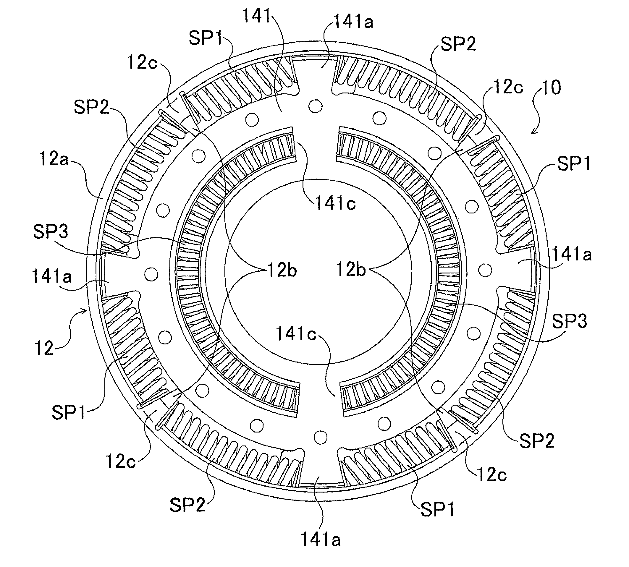
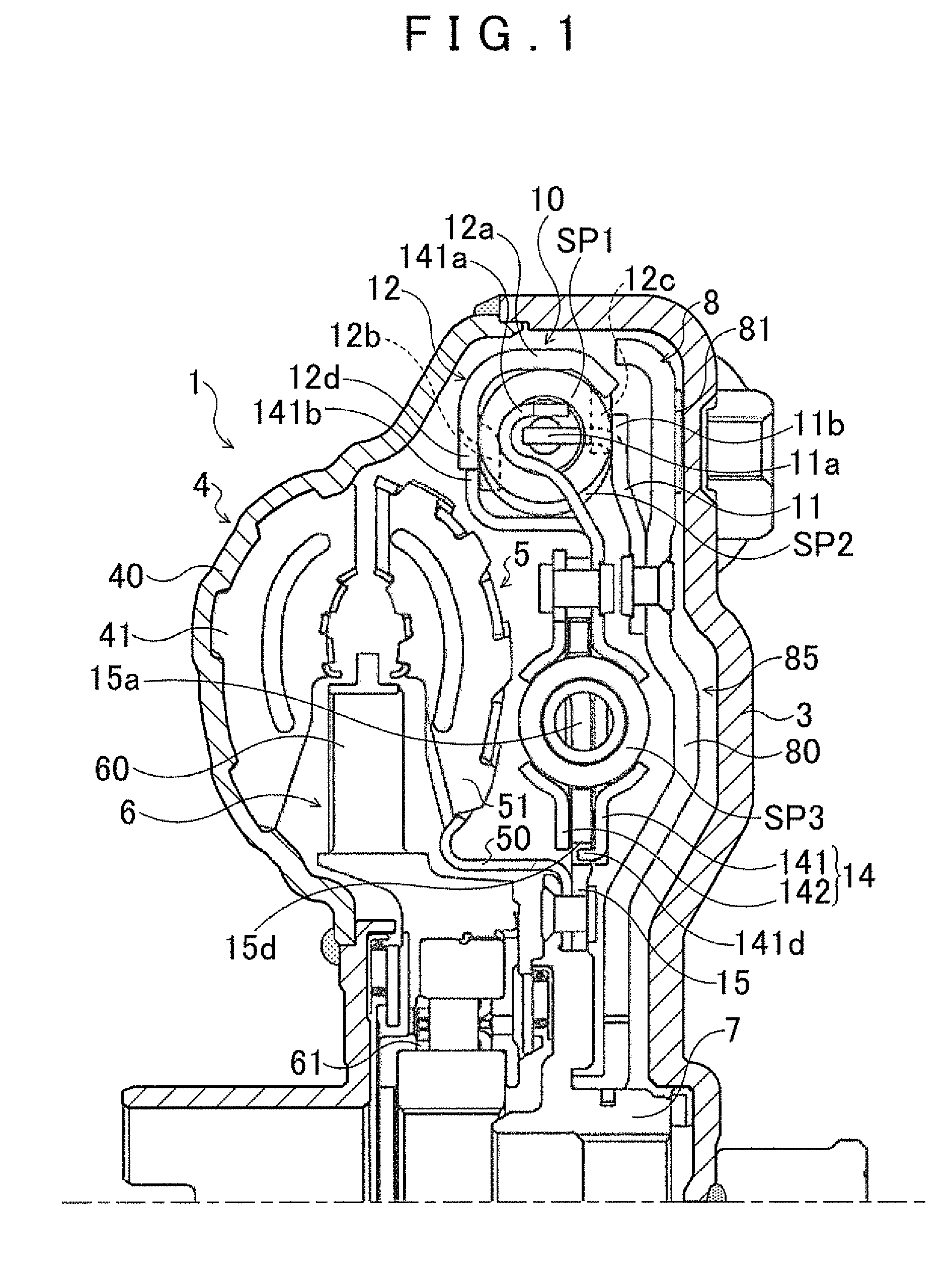
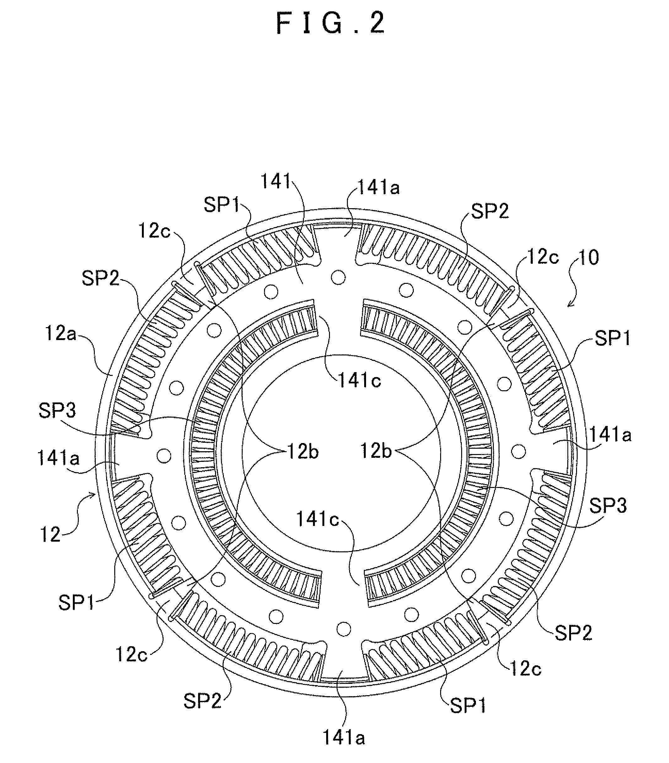
[0030]FIG. 1 is a construction diagram showing a fluid power transmission apparatus 1 equipped with a damper apparatus 10 according to an embodiment of the present invention. The fluid power transmission apparatus 1 shown in the drawing is a torque converter mounted as a starting device in a vehicle equipped with an engine (internal combustion engine) as a motor, and includes: a front cover (input member) 3 linked to a crankshaft of the engine (not shown); a pump impeller (input-side fluid power transmission element) 4 fixed to the front cover 3; a turbine runner (output-side fluid power transmission element) 5 that is rotatable coaxially with the pump impeller 4; a stator 6 that adjusts the flow of hydraulic oil (hydraulic fluid) from the turbine runner 5 to the pump impeller 4; a damper hub (output member) 7 fixed to an input shaft of a transmission apparatus (not shown) that is an automatic transmission (AT) or a ...


PUM


Abstract

In a damper apparatus, power is transferred, in order, from a motor, to an input, to a first elastic body, to a first element, to a second elastic body, to a second element, to a third elastic body, and to an output. The first and second elastic bodies are disposed radially outward of the third elastic body, and adjacent to each other on a single circumference. The first element has an annular outer peripheral portion that surrounds the first and second elastic bodies, and a pair of contact portions that are formed on peripheral edges on respective sides of the outer peripheral portion to protrude from the peripheral edges radially inward and to face each other, and that are between and in contact with the first elastic body and the second elastic body.

Description

INCORPORATION BY REFERENCE[0001]The disclosure of Japanese Patent Application No. 2011-070505 filed on Mar. 28, 2011 including the specification, drawings and abstract is incorporated herein by reference in its entirety.BACKGROUND OF THE INVENTION[0002]The present invention relates to a damper apparatus that includes an input element to which power is transferred from a motor, a first intermediate element to which power is transferred from the input element via a first elastic body, a second intermediate element to which power is transferred from the first intermediate element via a second elastic body, and an output element to which power is transferred from the second intermediate element via a third elastic body.DESCRIPTION OF THE RELATED ART[0003]As a fluid power transmission apparatus mounted in a vehicle, there has been known a torque converter equipped with a clutch mechanism for mechanically linking a front cover and a turbine to each other, and a damper apparatus made up of...

Claims


Application Information

Patent Timeline
Patent Type & Authority Patents(United States)
IPC IPC(8): F16F15/121
CPCF16H45/02F16F15/12366F16H2045/0205F16H2045/0231F16H2045/0294
Inventor TAKIKAWA, YOSHIHIROOI, YOICHIMARUYAMA, KAZUTOITOU, KAZUHIRO
Owner AISIN AW CO LTD
Why Eureka
Try Eureka