Pneumatic atomization system with rotatable spraying head

An atomization system, rotary atomization technology, applied in the direction of spraying device, spraying device, liquid spraying device, etc., can solve the problem of high toxicity

Active Publication Date: 2014-04-30
NAVY MEDICINE RES INST OF PLA +1
View PDF6 Cites 8 Cited by
  • Summary
  • Abstract
  • Description
  • Claims
  • Application Information

AI Technical Summary

Problems solved by technology

In some spraying operations with special requirements, such as highly toxic spraying liquid, confined space, etc., it is necessary for the spraying device to automatically rotate and spray to realize space spraying (spraying). Currently, the commonly used atomization systems cannot meet this requirement.

Method used


Image

  • Pneumatic atomization system with rotatable spraying head
  • Pneumatic atomization system with rotatable spraying head
  • Pneumatic atomization system with rotatable spraying head

Examples


Embodiment 1

[0032] Embodiment 1: Pneumatic atomization system of space spray mode with atomizing nozzle not rotating

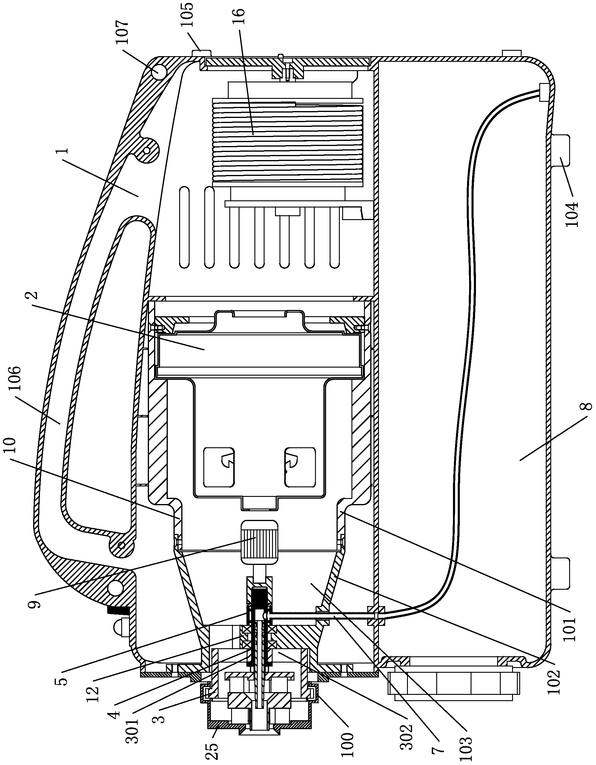
[0033] see figure 1 , 211, the pneumatic atomization system of 11, the casing 10 forming the air duct includes a rear end casing 101 and a tapered front end casing 102, the small end of the front end casing is the air duct outlet 103; the string used to generate high-speed airflow The excitation motor 2 is located in the rear end casing, and the front end of the series excitation motor 2 relative to the output shaft at the outlet of the air duct is provided with fan blades. The housing 10 is located inside the housing 1 . The upper space of the casing has a casing 10 and an automatic wire take-up device 16 . The automatic wire take-up device 16 is used to collect the power cord that provides power for the whole machine of the pneumatic atomization system.

[0034] Shell lower space is a medicine box 8. The medicine box 8 is integrated with the shell 1, and there is n...

Embodiment 2

[0050] Example 2: Pneumatic atomization system of stagnant spray mode with non-rotating atomizing nozzle

[0051] see image 3 , 12 、13. For the working status of the stagnant spray when the atomizing nozzle does not rotate, refer to image 3 , the main difference between it and Embodiment 1 is that it also includes a flexible air pipe 38 and a soft liquid pipe 39, and the two ends of the flexible air pipe 38 respectively pass through the quick installation joint 100 and the rear end of the skirt 272 of the atomizing nozzle, Rotate the snap ring for a detachable connection. The air duct communicates with the air inlet channel through the rotating snap ring and the soft air pipe. Both ends of the soft liquid pipe 39 communicate with the liquid inlet end 261 of the nozzle 26 and the transition pipe 40 respectively, and the transition pipe extends into the rotating liquid collecting rod 4 and communicates with the liquid collecting channel. The liquid medicine enters the nozz...

Embodiment 3

[0053] Example 3: Pneumatic atomization system with rotating spray head in space spray mode (rotatable spray head pneumatic atomization system)

[0054] For the spatial spray state of atomizing nozzle rotation, refer to Figure 4 , 5 The main difference between it and Embodiment 1 is that it also includes a hard curved pipe 6, and the two ends of the hard curved pipe 6 are respectively connected to the rear end of the skirt 272 of the atomizing nozzle and the rotating snap ring 3 through the quick installation joint 100. Detachable connection; at the same time, when the rotating card rotates clockwise (or counterclockwise) around the axis, it can drive the hard curved pipe to rotate with the rotating snap ring, and the hard curved pipe can drive the skirt to rotate with the hard curved pipe. There are many kinds of connection structures (quick installation joints) that can be rotated clockwise (or counterclockwise) together and detachable between the hard elbow and the rotati...


PUM


Abstract

The invention provides a pneumatic atomization system with a rotatable spraying head. The pneumatic atomization system with the rotatable spraying head can achieve spatial spraying in a large space and comprises a main power device. A rotating liquid collection rod is located in a rotating clamping ring and connected with the rotating clamping ring, and the rotating liquid collection rod and the rotating clamping ring can rotate relative to an air passage. The atomization spraying head is connected to one end of the rotating clamping ring and provided with a nozzle and an air inlet passage for atomizing pesticide liquid sprayed out of the nozzle. The air passage is communicated with an air inlet passage of the atomization spraying head through an inner cavity of the rotating clamping ring. A liquid collection passage is formed in the rotating liquid collection rod. A liquid collection base located in the air passage is provided with a liquid collection cavity. The rotating liquid collection rod penetrates through the liquid collection cavity and is provided with a hole passage through which the liquid collection passage is communicated with the liquid collection cavity. The periphery of the rotating liquid collection rod makes sealing contact with the liquid collection base in a rotating mode. A liquid inlet of the nozzle is communicated with the liquid collection passage. The liquid collection cavity is communicated with a pesticide box through a liquid inlet pipe. A rotation power device used for driving the rotating liquid collection rod to rotate is arranged in the air passage.

Description

technical field [0001] This technology involves spraying or atomizing devices. Background technique [0002] At present, the most widely used atomization systems in nebulizers mainly include the following three types: air flow atomization system, pressure atomization system and rotary atomization system. The air atomization system relies on the friction force generated by the speed difference between the gas and the liquid, and the liquid is pulled into long and thin filaments in an instant, and these liquid filaments are quickly broken at the thinner points to form tiny mist droplets. The air-flow atomization system can produce highly uniform droplets with a small average particle size, and has a simple structure and high reliability, which is unmatched by the other two atomization systems. At present, the rotary spray technology mentioned mainly refers to the high-speed rotary equipment to atomize the feed liquid into micron-sized droplets, rather than the atomization sys...

Claims


Application Information

Patent Timeline
Patent Type & Authority Applications(China)
IPC IPC(8): B05B3/02B05B13/02
CPCB05B1/06B05B3/02B05B7/0483B05B7/0823B05B7/1209B05B12/02
Inventor 崔业民张建郝蕙玲孙锦程王猛茹煜吕鸿雁周宏平许林云崔华
Owner NAVY MEDICINE RES INST OF PLA
Why Eureka
Try Eureka