Casting and welding mechanism of storage battery casting and welding machine

A casting welding machine and battery technology, applied in the field of battery processing equipment components, can solve the problems of low efficiency, high pollution risk, large labor demand, etc., and achieve the effects of controllable heating temperature, clean working environment, stable and reliable technology

Inactive Publication Date: 2014-04-30
ZHANGJIAGANG ZHIZHOU IND TECH
View PDF7 Cites 4 Cited by
  • Summary
  • Abstract
  • Description
  • Claims
  • Application Information

AI Technical Summary

Problems solved by technology

[0002] In the production process of the battery, the welding between the tabs of the battery plate group is a very critical process, that is, the busbar casting and welding technology. The traditional process is manual welding. With the application range of lead-acid batteries Continuously expanding, the requirements for product quality are further improved. In the production process of small and medium-sized lead-acid batteries, the quality and efficiency of electrode group welding is one of the important factors affecting the overall quality of products and production efficiency. At present, most medium-density lead-acid batteries Among manufacturers, manual welding is still an important method of extreme group welding. This welding method results in poor production and operation environment, high pollution risk, large labor demand, direct contact between workers and lead substances, and a greater risk of physical injury to workers, and extreme group welding The quality is different and the efficiency is low. It is obvious that the continuous improvement and popularization of mechanized automatic welding of lead-acid batteries can effectively improve production efficiency, ensure product quality, protect the health of workers, and achieve clean production. At present, there are small-density lead-acid batteries on the market. Automatic casting and welding machines, but most of the products only realize the welding of the busbar, and do not realize the simultaneous welding of the bridge and the busbar

Method used


Image

  • Casting and welding mechanism of storage battery casting and welding machine
  • Casting and welding mechanism of storage battery casting and welding machine
  • Casting and welding mechanism of storage battery casting and welding machine

Examples


Embodiment Construction

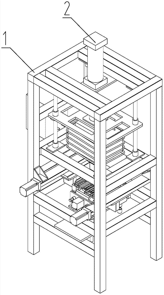
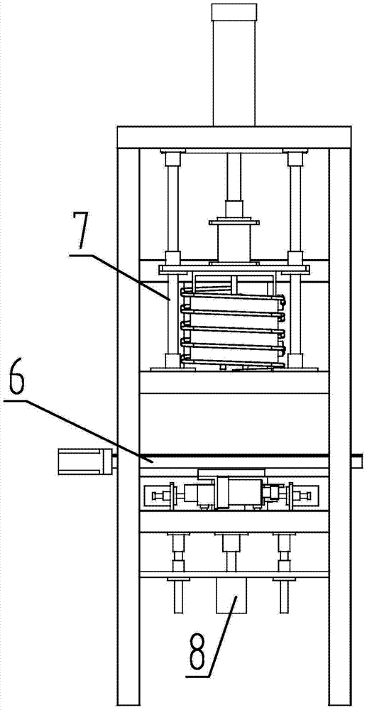
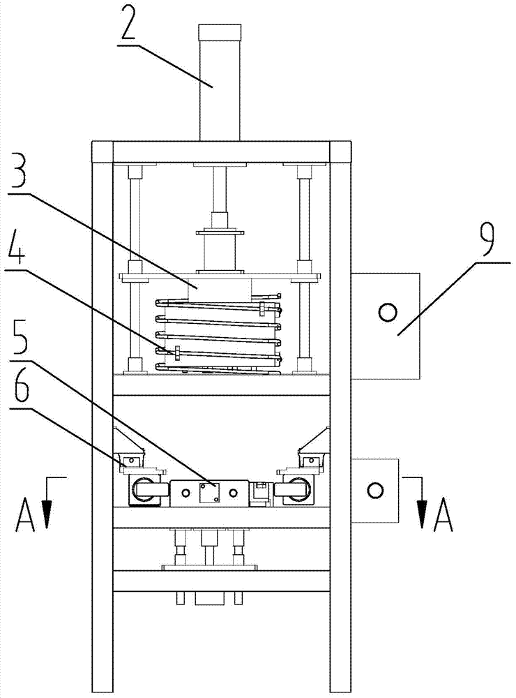
[0018] Such as figure 1 -- Figure 5 As shown, the casting and welding mechanism of the battery casting and welding machine of this embodiment includes a frame 1, a lead supply device 3, a casting and welding mold device 5, a battery positioning device 6, and two eddy current induction heating devices 9 , two eddy current induction coils 4 and 10, and a lead box moving device, the described lead supply device is installed on the connecting plate of the lead box moving device, and the described battery positioning device is installed on the positive side of the described lead supply device Below, the casting and welding mold device is installed below the battery positioning device, and the two eddy current induction coils are respectively installed on the outside of the lead supply box of the described lead supply device and the casting and welding of the casting and welding mold device. On the upper surface of the mould, two eddy current induction heating devices are respecti...


PUM


Abstract

The invention relates to battery processing equipment assemblies, particularly to a casting and welding mechanism of a storage battery casting and welding machine. The casting and welding mechanism comprises a frame, a lead supplying device, a casting and welding mould device, a battery positioning device, two eddy sensing heating devices, two eddy sensing coils and a lead box moving device. The lead supplying device is mounted on the connecting board of the lead box moving device, the battery positioning device is arranged right under the lead supplying device, the casting and welding mould device is mounted under the battery positioning device, the two eddy sensing coils are mounted outside the lead supplying box of the lead supplying device and on the upper surface of the casting and welding mould of the casting and welding mould device respectively, and the two eddy sensing heating devices are connected with the two eddy sensing coils respectively.

Description

technical field [0001] The invention relates to a battery processing equipment assembly, in particular to a casting and welding mechanism of a storage battery casting and welding machine. Background technique [0002] In the production process of the battery, the welding between the tabs of the battery plate group is a very critical process, that is, the bus bar casting welding technology. The traditional process is manual welding. With the application range of lead-acid batteries Continuously expanding, the requirements for product quality are further improved. In the production process of small and medium-sized lead-acid batteries, the quality and efficiency of electrode group welding is one of the important factors affecting the overall quality of products and production efficiency. At present, most medium-density lead-acid batteries Among manufacturers, manual welding is still an important method of pole group welding. This welding method causes poor production and opera...

Claims


Application Information

Patent Timeline
Patent Type & Authority Applications(China)
IPC IPC(8): B22D19/04
Inventor 向伟
Owner ZHANGJIAGANG ZHIZHOU IND TECH
Why Eureka
Try Eureka