
Heat exchanger

a heat exchanger and heat exchanger technology, applied in the field of heat exchangers, can solve the problem that the device is not readily made more compact, and achieve the effect of compactness and limited manufacturing costs of the heat exchanger according to the fourth through sixth aspect of the present invention

Inactive Publication Date: 2014-06-26
DAIKIN IND LTD
View PDF9 Cites 17 Cited by
  • Summary
  • Abstract
  • Description
  • Claims
  • Application Information

AI Technical Summary

Benefits of technology

The heat exchanger in this patent can be made smaller and more efficient. The manufacturing costs of certain aspects of the heat exchanger can be limited.

Problems solved by technology

The header must therefore be lengthened in cases where a plurality of the flat porous tubes are linked to the header, and the device is not readily made more compact.

Method used


Image

  • Heat exchanger
  • Heat exchanger
  • Heat exchanger

Examples


Embodiment Construction

[0030]An embodiment of a heat exchanger according to the present invention will be described below on the basis of the drawings. The embodiment of the heat exchanger according to the present invention is a specific example of the present invention and does not limit the technical scope of the present invention.

[0031](1) Configuration of Air-Conditioning Device

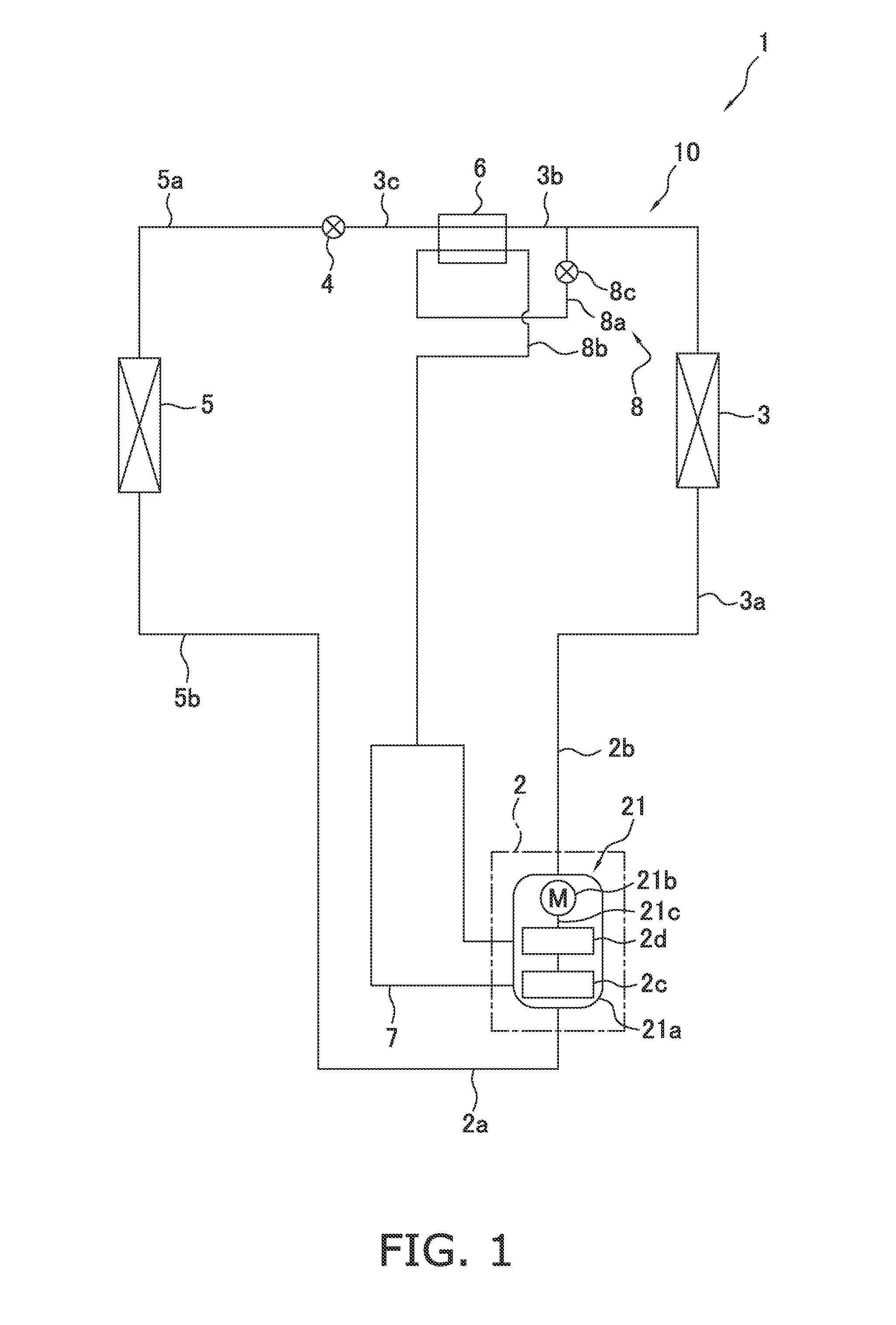
[0032]FIG. 1 is a schematic diagram of an air-conditioning device 1 that serves as an example of a refrigerating device provided with a heat exchanger according to the present invention. The air-conditioning device 1 has a refrigerant circuit 10 configured so as to allow air-cooling operations, uses carbon dioxide or another refrigerant active in the supercritical region, and performs a two-stage compression refrigeration cycle. The refrigerant circuit 10 primarily has a compression mechanism 2, a heat-source-side heat exchanger 3, an expansion mechanism 4, a usage-side heat exchanger 5, and an economizer heat exchanger 6. Thes...


PUM


Abstract

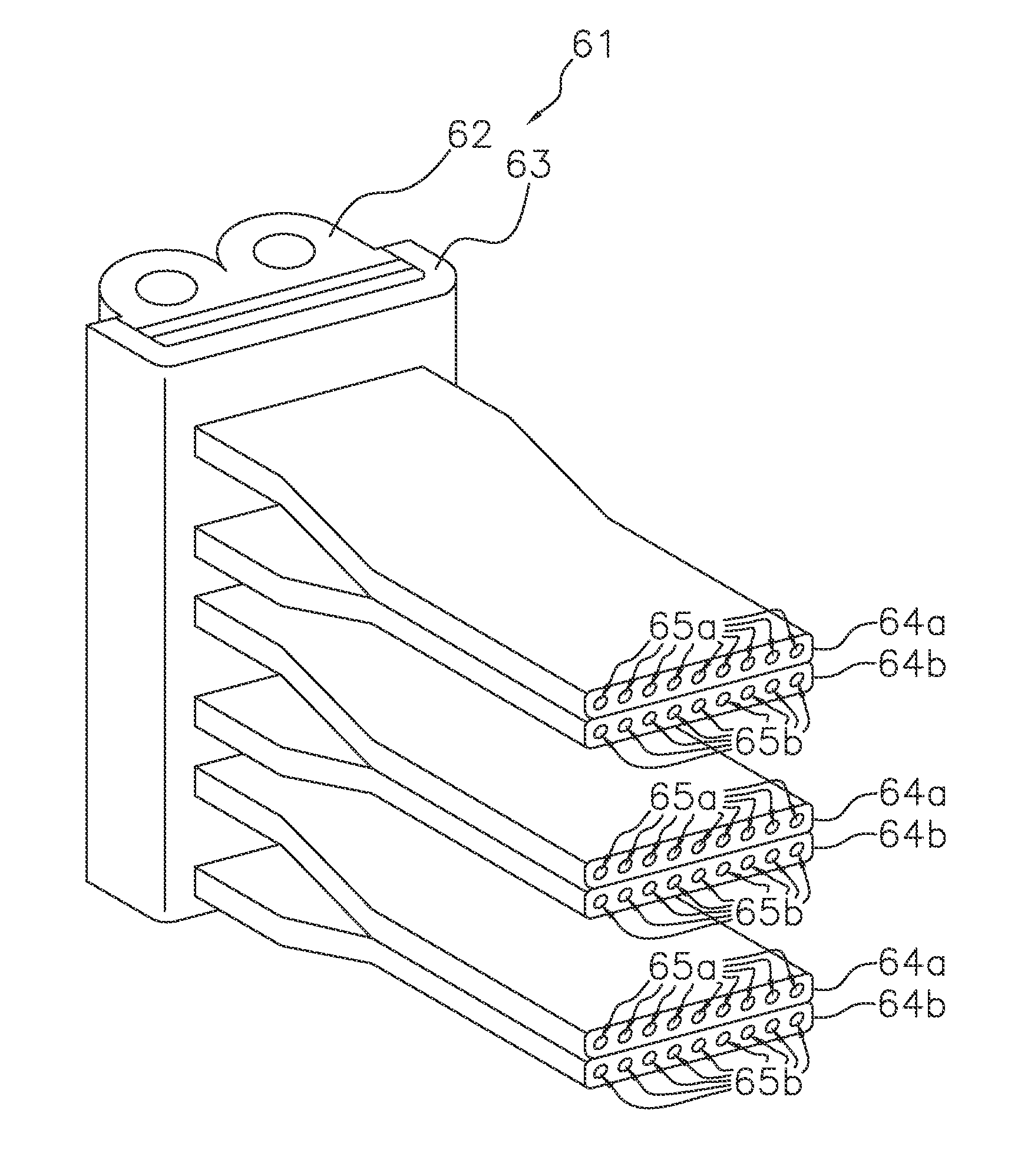
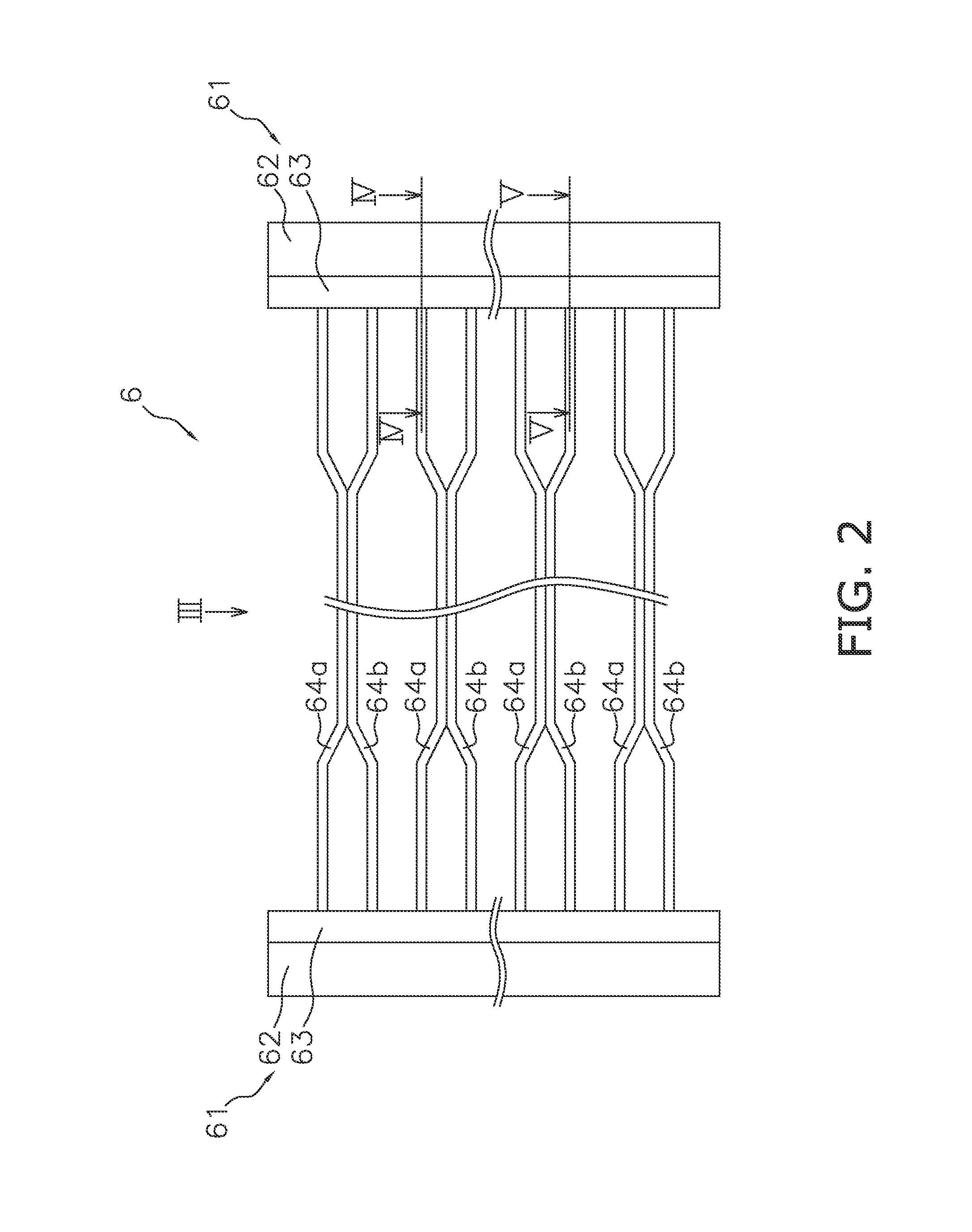
A heat exchanger includes a header, a first flat porous tube, and a second flat porous tube. The header has first and second primary channels, with first and second refrigerants flowing through the first and second primary channels. The first flat porous tube has a plurality of first refrigerant-channel holes through which the first refrigerant flows. The second flat porous tube has a plurality of second refrigerant-channel holes through which the second refrigerant flows. The header has sub-channel-forming member that forms a first sub-channel and a second sub-channel. The first sub-channel allows the first primary channel to be communicated with the first refrigerant-channel holes. The second sub-channel allows the second primary channel to be communicated with the second refrigerant-channel holes. The first flat porous tube and the second flat porous tube are in close contact to allow heat exchange between the first refrigerant and the second refrigerant.

Description

TECHNICAL FIELD[0001]The present invention relates to a heat exchanger.BACKGROUND ART[0002]Heat exchangers that use flat porous tubes to allow heat exchange between a refrigerant and a refrigerant are conventionally used in refrigeration cycles, as disclosed in Patent Document 1 (Japanese Laid-Open Patent Application No. 2007-163004). Two flat porous tubes, through which flow two respective types of refrigerant that are subjected to heat exchange, are bonded together in these heat exchangers. The flat porous tubes in these heat exchangers are linked to a header so that the alignment direction of refrigerant flow-channel holes of the flat porous tubes proceeds along a longitudinal direction of the header. The header must therefore be lengthened in cases where a plurality of the flat porous tubes are linked to the header, and the device is not readily made more compact.SUMMARY OF THE INVENTIONProblems to be Solved by the Invention[0003]It is an object of the present invention to provi...

Claims


Application Information

Patent Timeline
Patent Type & Authority Applications(United States)
IPC IPC(8): F28F1/02
CPCF28F1/022F28D7/0033F28F9/0221F28F9/0243F28F9/0278F28D1/0426F28D1/05383F28F1/025F25B2400/13F25B1/10
Inventor YOSHIOKA, SHUNKAJI, RYUHEISHIRAISHI, YOSHIKAZUFUJIWARA, AKIHIROHYOUDOU, TAKAYUKI
Owner DAIKIN IND LTD
Learn More