Double-crank flying shear mechanism with instinct of automatically eliminating mechanism movement dead points

A double crank, motion technology, applied in the field of metallurgical enterprises, can solve the problems of difficult to achieve complete equality, difficult to make phases, etc.

Inactive Publication Date: 2014-04-30
王利霞 +2
View PDF0 Cites 3 Cited by
  • Summary
  • Abstract
  • Description
  • Claims
  • Application Information

AI Technical Summary

Problems solved by technology

However, figure 1 or figure 2 crank in r 1 with crank r 2 It is difficult to make the lengths of the rods exactly equal; and the length o

Method used


Image

  • Double-crank flying shear mechanism with instinct of automatically eliminating mechanism movement dead points
  • Double-crank flying shear mechanism with instinct of automatically eliminating mechanism movement dead points
  • Double-crank flying shear mechanism with instinct of automatically eliminating mechanism movement dead points

Examples


Example Embodiment

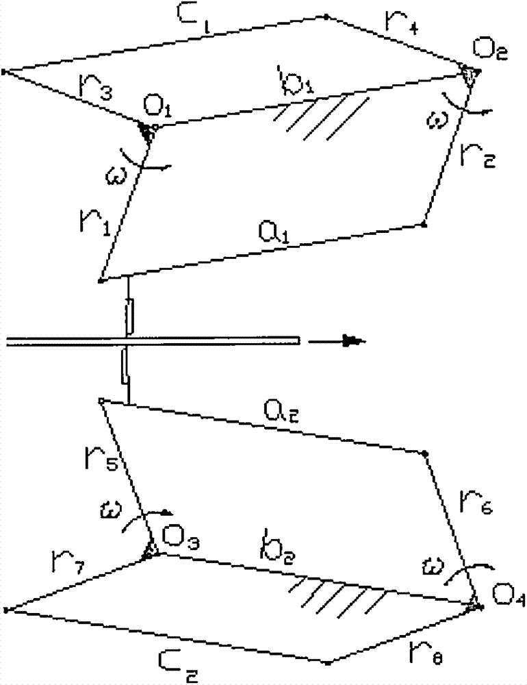
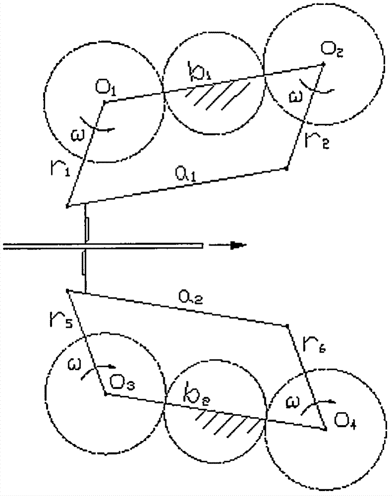
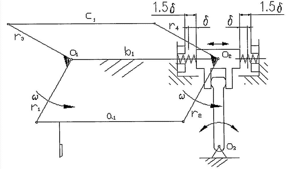
[0010] The present invention includes two sets of plans A and B (see plan A image 3 and Figure 4 ; See plan B Figure 5 and Image 6 ). The common feature is that one of the center of the driving crankshaft and the center of the driven crankshaft remains stationary, and the center of the other crankshaft can approach or move away from the center of the stationary crankshaft along the line connecting the two centers. It is assumed that the above two sets of schemes assume the center of the active crankshaft O 1 Do not move. Support driven crankshaft O 2 There are two bearing seats in total (it can be more than two, the principle remains the same), each of which is a sliding block. When the mechanism reaches the dead point of motion, it can be automatically and synchronized from the nominal position to or away from the active crankshaft center. 1 Move a small distance δ, so that the mechanism smoothly rushes through the corresponding dead point. In order to make the above two b...


PUM


Abstract

The invention relates to a double-crank flying shear mechanism with an instinct of automatically eliminating mechanism movement dead points. One of two cranks of the mechanism is movable, and at least two corresponding bearing blocks supporting the moving crank become sliders, and can be driven by the moving crank to move on a body. In order to ensure the sliders to synchronize on one side during movement, a mechanical synchronizer is arranged. An axis of the moving crank is ensured to be always parallel to an axis of the non-moving crank. Therefore, necessary conditions are created for a novel shearing mechanism to easily cross the mechanism movement dead points. The problem that two sets of past shearing mechanisms in specifications cannot cross the mechanism movement dead points easily is solved satisfactorily. The novel fly shear mechanism is mainly used for shearing metal in movement just like the past shearing mechanisms, thereby still belonging to mechanical equipment in the metallurgy industry. Whether or not the related principle of the novel mechanism can be further applied to other occasions is still unclear at present.

Description

technical field [0001] The flying shear is mainly used in the metallurgical industry. It is a common equipment in the rolling workshop. It is a machine for transversely shearing the running metal strip or other cross-section billets. The invention relates to a brand-new flying shear mechanism of the technical solution. There are two sets of schemes, namely scheme A and scheme B. The principle is attached image 3 and 5 . Properly combining the flying shear mechanism involved in the present invention and installing other related components can form a brand-new flying shear of the above-mentioned principle. After the invention is implemented, it can still be used in metallurgical enterprises. Background technique [0002] The present invention is respectively improved from the double-crank flying shears that are common in metallurgical enterprises and described in rolling textbooks. For the two sets of schematic diagrams of the original double-crank flying shears, please r...

Claims


Application Information

Patent Timeline
IPC IPC(8): B23D25/08B23Q5/02
Inventor 不公告发明人
Owner 王利霞
Why Eureka
Try Eureka