
Method and system for calibrating train wheel diameter

A calibration method and calibration system technology, applied in the direction of wheel rim measurement/measurement, can solve the problems of wheel diameter change, train wheel wear, affecting wheel diameter calibration accuracy, etc., to improve accuracy, increase flexibility, ensure correctness effect

Active Publication Date: 2014-04-30
浙江众合科技股份有限公司
View PDF5 Cites 25 Cited by
  • Summary
  • Abstract
  • Description
  • Claims
  • Application Information

AI Technical Summary

Problems solved by technology

[0003] Due to the wear and tear of the wheels of the train during the running of the train, the wheel diameter will also change. In the existing wheel diameter calibration method, two or more special wheel diameter calibration beacons that are pre-laid on the track are required. , the distance used for speed measurement is determined by two beacons, and the wheel diameter of the train is calculated according to the pulse generated in the process of passing through the two beacons, but this method has the following disadvantages: 1) The beacon installed for wheel diameter calibration The position must have high precision, which will increase the difficulty of engineering and the cost of the beacon; 2) The beacon query device will produce a certain deviation when locking the position of the beacon, which will affect the accuracy of the wheel diameter calibration calculation results; 3) Generally, the signal The mark is placed on the straight track of the conversion rail, and is used for wheel diameter calibration before the train enters the main line. If the train is restarted after the system brakes midway, the wheel diameter calibration cannot be performed again; 4) During the wheel diameter calibration process In the process, if there are phenomena such as idling and slipping, it will directly affect the accuracy of wheel diameter calibration

Method used


Image

  • Method and system for calibrating train wheel diameter
  • Method and system for calibrating train wheel diameter

Examples


Embodiment Construction

[0035] In order to make the above objects, features and advantages of the present invention more comprehensible, specific implementations of the present invention will be described in detail below in conjunction with the accompanying drawings.

[0036] In the following description, numerous specific details are set forth in order to provide a thorough understanding of the present invention. However, the present invention can be implemented in many other ways different from those described here, and those skilled in the art can make similar extensions without violating the connotation of the present invention, so the present invention is not limited by the specific implementations disclosed below.

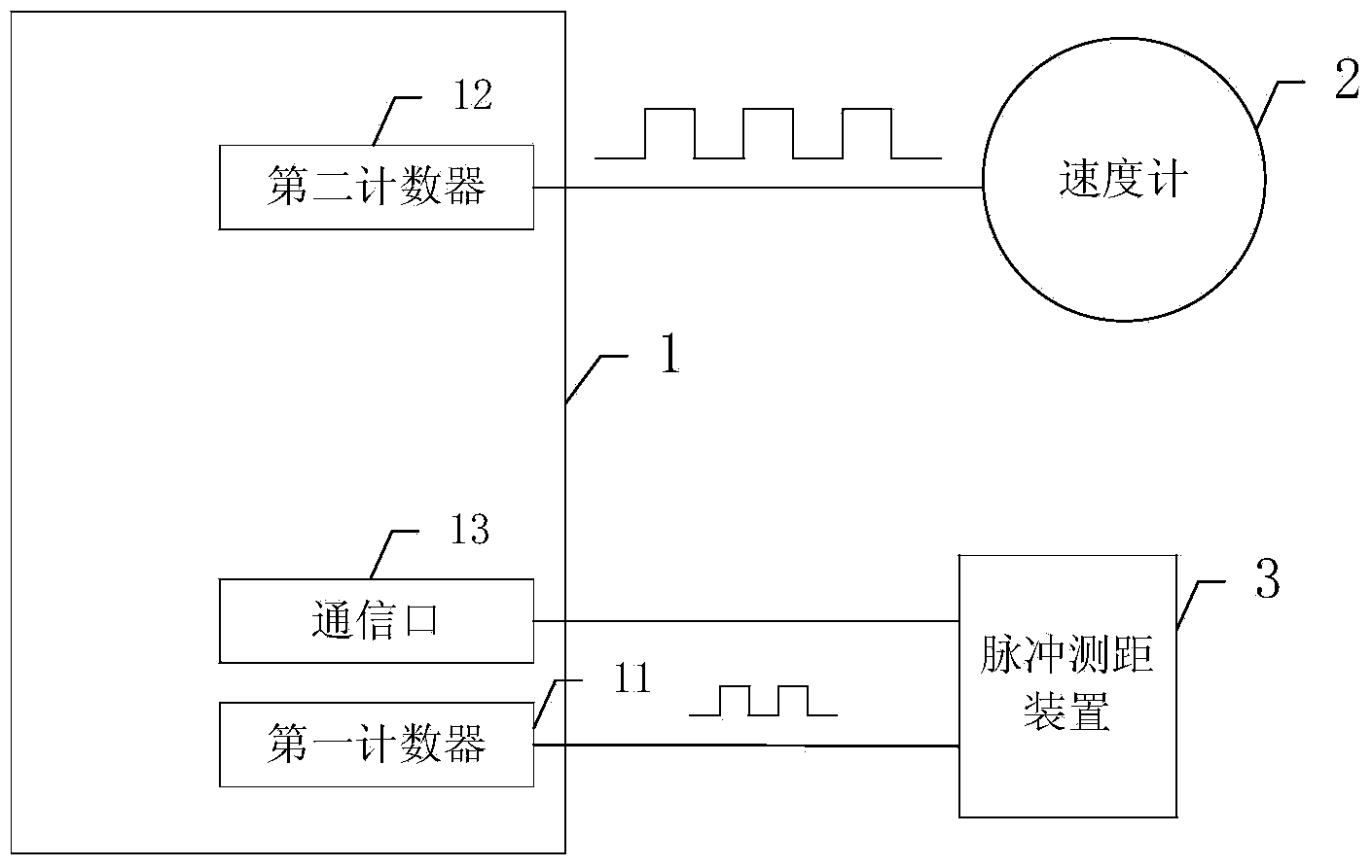
[0037] figure 1 It shows a structural block diagram of a calibration system for a train wheel diameter in an embodiment of the present invention, including: a pulse distance measuring device 3, the first output end of the pulse distance measuring device 3 outputs pulse distance meas...


PUM


Abstract

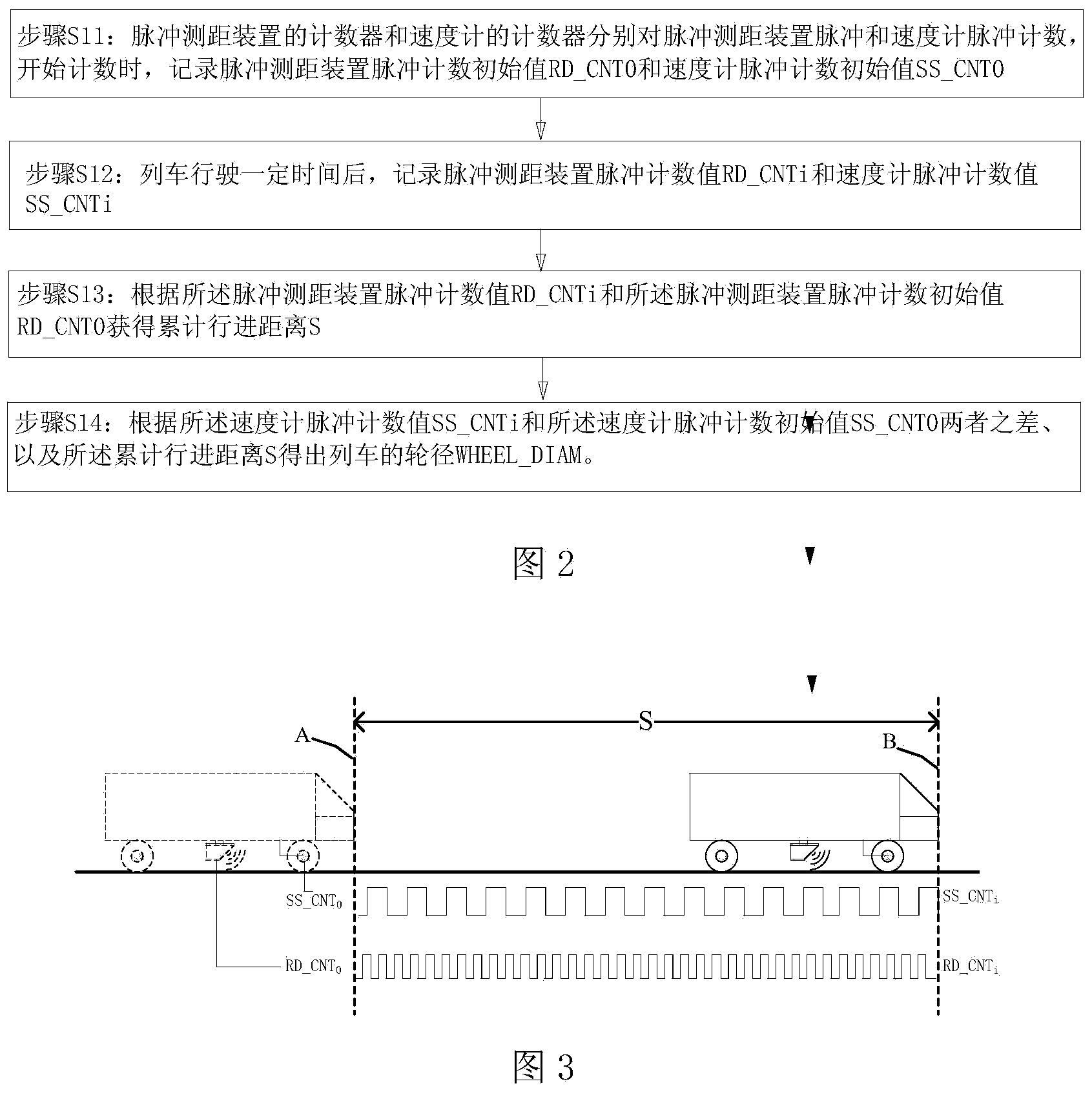
The invention discloses a method and system for calibrating the train wheel diameter. The method comprises the following steps that firstly, a counter of a pulse distance measuring device and a counter of a speedometer are used for counting pulses of the pulse distance measuring device and pulses of the speedometer respectively, and when the counting is started, the pulse counting initial value of the pulse distance measuring device and the pulse counting initial value of the speedometer are recorded at the same time; secondly, after a train is driven for certain time, the pulse counting value of the pulse distance measuring device and the pulse counting value of the speedometer are recorded at the same time; thirdly, the train accumulation advancing distance is obtained according to the pulse counting value of the pulse distance measuring device and the pulse counting initial value of the speedometer; fourthly, the wheel diameter of the train is obtained according to the difference between the pulse counting value of the speedometer and the pulse counting initial value of the speedometer and the train accumulation advancing distance. Wheel diameter calibration can be carried out at any time in the driving process of the train, and the precision of wheel diameter calibration is improved.

Description

technical field [0001] The invention relates to the field of train wheel diameter calibration, in particular to a train wheel diameter calibration method and a calibration system. Background technique [0002] In the urban rail transit application system, the speed measurement of the train is realized by the speedometer. The working principle of the speedometer is: a fixed number of pulses will be generated when the wheel rotates once. The number counted by the counter can know the distance traveled and further obtain the speed of the train. Therefore, the diameter of the train wheel directly affects the accuracy of the measurement result. [0003] Due to the wear and tear of the wheels of the train during the running of the train, the wheel diameter will also change. In the existing wheel diameter calibration method, two or more special wheel diameter calibration beacons that are pre-laid on the track are required. , the distance used for speed measurement is determined by...

Claims


Application Information

Patent Timeline
IPC IPC(8): B61K9/12
Inventor 许明李焕逸张鑫
Owner 浙江众合科技股份有限公司
Learn More