Engine radiating mechanism for unmanned aerial vehicles

A heat dissipation mechanism and engine technology, applied in the direction of machine/engine, engine components, engine cooling, etc., can solve the problems of reduced cooperation gap between moving parts, potential safety hazards, unmanned aerial vehicles cannot be used for a long time, etc., to achieve heat dissipation High efficiency and safe effect

Inactive Publication Date: 2014-04-30
EWATT TECH CO LTD
View PDF5 Cites 31 Cited by
  • Summary
  • Abstract
  • Description
  • Claims
  • Application Information

AI Technical Summary

Problems solved by technology

Therefore, UAVs have high requirements for engines, but at present, during the use of UAV engines, there is no good heat dissipation device, which makes UAVs unable to be used for a long time, and excessive engine temperature will lead to the coordination between mutual moving parts. The gap is reduced, which hinders the normal movement of the machine parts, and even causes the moving parts to be stuck, resulting in potential safety hazards

Method used


Image

  • Engine radiating mechanism for unmanned aerial vehicles
  • Engine radiating mechanism for unmanned aerial vehicles

Examples


Embodiment Construction

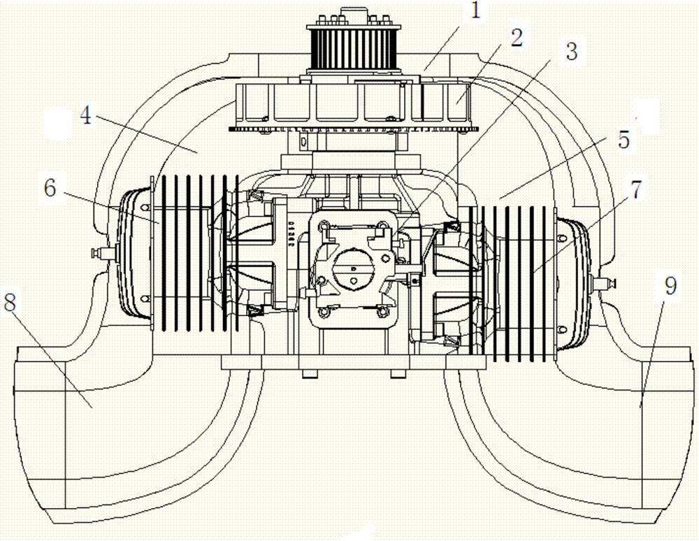
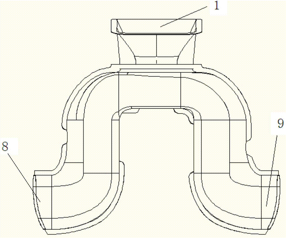
[0016] see Figure 1-2 , the embodiment of the present invention provides a UAV engine heat dissipation mechanism, including a casing structure, an engine 3 and a fan 2 . The first heat dissipation cover and the second heat dissipation cover are packaged. The first heat dissipation cover is connected with the second heat dissipation cover through bolts. The first cooling cover and the second cooling cover form the air inlet 1 and the outlet end. Air intake 1 is located above the fuselage. The air outlet is located on both sides of the fuselage. The fan 2 is arranged below the air inlet 1 . The area of ​​the fan 2 is larger than the area of ​​the air inlet 1. The fan 2 is connected to the motor 3 through a shaft, and the motor 3 drives the fan 2 to work, so there is no need to install another motor for the fan. The gas outlet includes a first gas outlet 8 and a second gas outlet 9 . The first air outlet 8 and the second air outlet 9 are respectively located on two sides ...


PUM


Abstract

The invention discloses an engine radiating mechanism for unmanned aerial vehicles and belongs to the technical field of heat dissipation for engines of unmanned aerial vehicles. The engine radiating mechanism for unmanned aerial vehicles comprises an enclosure structure, an engine and a fan; the fan and the engine are disposed within the enclosure structure; the engine is connected with the fan. The engine radiating mechanism for unmanned aerial vehicles is capable of radiating for the engine, radiating efficiency is high, and safety of the engine is guaranteed.

Description

technical field [0001] The invention relates to the technical field of unmanned aerial vehicle engine heat dissipation, in particular to an unmanned aerial vehicle engine heat dissipation mechanism. Background technique [0002] Unmanned aircraft, referred to as "UAV", is an unmanned aircraft controlled by radio remote control equipment and its own program control device. There is no cockpit on board, but equipment such as autopilot and program control device are installed. The personnel on the ground, on the ship, or at the remote control station of the parent aircraft track, locate, remotely control, telemeter and digitally transmit it through radar and other equipment. Under the radio control, it can take off like an ordinary aircraft or be launched into the air with a booster rocket, and it can also be taken into the air by the parent aircraft for flight. When recovering, it can automatically land in the same way as the common aircraft landing process, and can also be ...

Claims


Application Information

Patent Timeline
Patent Type & Authority Applications(China)
IPC IPC(8): B64D33/10
CPCB64D33/10F01P5/02F01P5/04F01P5/06F01P2050/20H02K9/14B64D33/08B64U50/11
Inventor 赵国成丹尼斯·费特斯
Owner EWATT TECH CO LTD
Why Eureka
Try Eureka