
Dust suppression and removal combined device for drop points of belt conveyors

A technology of belt conveyor and dust removal device, which is applied in the direction of conveyor objects, transportation and packaging, loading/unloading, etc., can solve the problems that are not conducive to the long-term stability of the system, the filter bag loses the filtering function, and the potential energy of the material cannot be eliminated. The effect of dust reduction is obvious, the effect of dust collection is improved, and the effect of dust removal is improved

Active Publication Date: 2014-04-30
PINGAN ELECTRICAL
View PDF7 Cites 6 Cited by
  • Summary
  • Abstract
  • Description
  • Claims
  • Application Information

AI Technical Summary

Problems solved by technology

[0003] 1. During the transportation of the material, the inertia generated when it is separated from the belt causes the dust to separate from the material and cause flying
[0004] 2. The operation of the belt and mechanical device of the conveyor, and the air flow carried by it, cause the dust in the material to fly
While cleaning the dust, the filter bag will also lose its filtering function instantaneously, which is not conducive to the long-term and stable operation of the system
[0014] 4. When the dust is discharged from a high place to a low place, the potential energy generated by the drop of the material cannot be eliminated, and the kinetic energy generated by falling on the receiving belt conveyor always exists the possibility of causing the dust to fly

Method used


Image

  • Dust suppression and removal combined device for drop points of belt conveyors
  • Dust suppression and removal combined device for drop points of belt conveyors
  • Dust suppression and removal combined device for drop points of belt conveyors

Examples


Embodiment 1

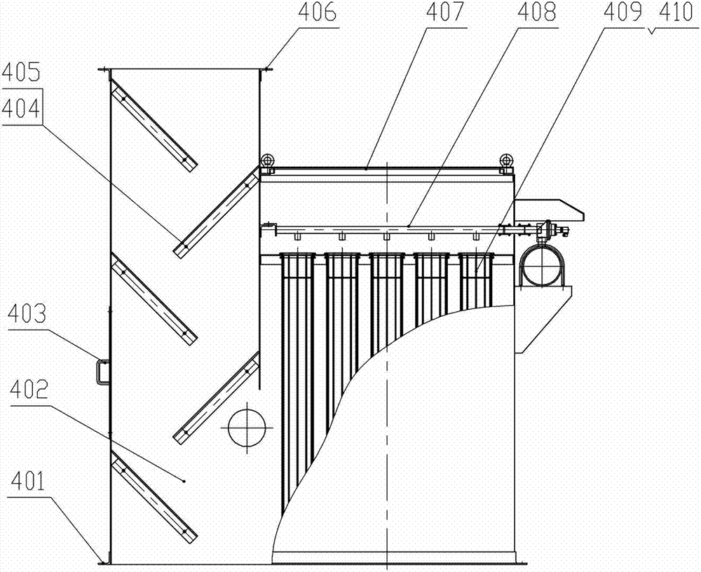
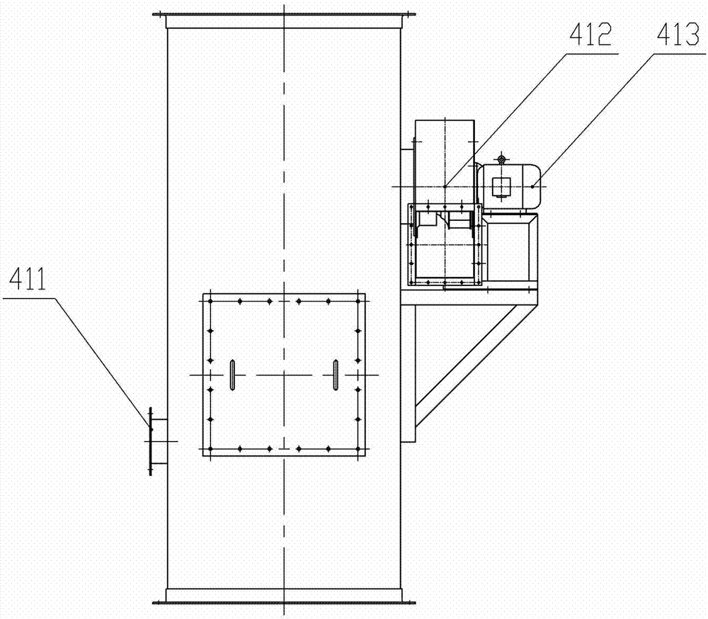
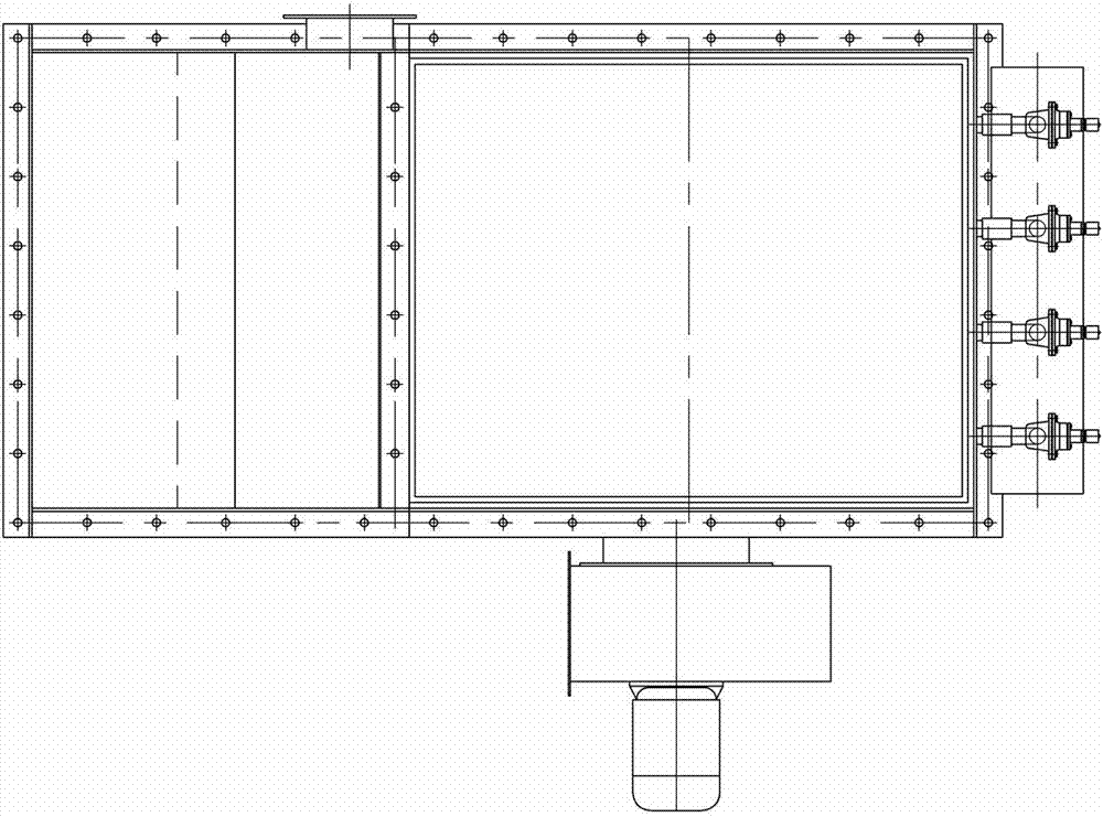
[0040] Embodiment 1, the present invention includes a box body 402, a fan 413 arranged on one side of the box body 402, and lower flanges 401 and upper flanges 406 at both ends of the box body 402, and the falling pipe and the housing of the dust collector are designed to be combined Structure, the box body 402 is divided into two parts by a partition in the middle, the blanking tube and the dust removal chamber. The wall of the blanking tube is staggered left and right or in steps, and there are more than two baffle brackets 404 that slope downward at a certain angle. A wear-resistant liner 405 is provided on the plate support 404; the upper end of the dust removal chamber is lower than the blanking pipe, and is divided into upper and lower chambers by an orifice plate. The dust removal device 408 is arranged on the upper part of the dust removal chamber. More than 2 columns and more than 2 rows of vertically parallel filter bags are arranged in the holes, which are supported ...

Embodiment 2

[0042] Embodiment 2, the present invention is installed in the unloading trough of the upper belt conveyor with a certain drop and the receiving chute of the lower belt conveyor, airtight covers are respectively arranged at the unloading chute and the receiving chute, and the upper airtight cover is provided with The dust suction branch pipe is connected with the air inlet under the cabinet. The upper end of the box body 402 is fixedly connected with the upper sealing cover 3 through the upper flange 406 , and the lower end is fixedly connected with the lower sealing cover 5 through the lower flange 401 . refer to Figure 1 to Figure 5 , all the other are with embodiment 1.


PUM


Abstract

A dust suppression and removal combined device for drop points of belt conveyors. The dust suppression and removal combined device for the drop points of the belt conveyors mainly solves technical problems of complex structure, ineffectiveness and the like of an existing dust suppression and removal device. The main points of the technical scheme of the dust suppression and removal combined device for the drop points of the belt conveyors include that a blanking tube of the belt conveyor and a bag filter are combined, a box (402) is separated into two portions through a separation plate. Two or more blocking plate supports (404) sloping downwards at a certain angle are arranged on the inner wall of the blanking tube in a left-right staggered and stepped mode and provided with abrasion-resistant lining plates (405); a dust removal chamber is provided with a filter bag (409), a filter bag frame (410) and a dust cleaning device (408). The dust suppression and removal combined device is mounted on the blanking place of the two belt conveyors with a certain drop. The dust rose during blanking can be reduced through deflection baffles, the rose dust in an upper closing cover, a lower closing cover and the blanking tube is sucked and collected for purification through the negative pressure generated by a draught fan dust of the dust removal device. The dust suppression and removal combined device for the drop points of the belt conveyors is mainly used for dust suppression and removal in the process of feed conveying at the drop points of the belt conveyors.

Description

technical field [0001] The invention relates to a combined dust suppression and dust removal device for the drop point of a belt conveyor. Background technique [0002] At present, belt conveyors with large specifications and long-distance transportation often have multiple transfer stations during the transportation process, and there is a certain drop between the front and rear belt conveyors. When the material is unloaded from a high place to a low place, a certain amount of dust will always be generated near the belt conveyor. As the height difference of the drop point increases, the amount of dust will increase. The main reasons for the generation of dust are as follows: [0003] 1. During the transportation of the material, the inertia generated when it is separated from the belt causes the dust to separate from the material and cause flying [0004] 2. The operation of the belt and mechanical device of the conveyor, and the air flow carried by it, cause the dust in ...

Claims


Application Information

Patent Timeline
Patent Type & Authority Applications(China)
IPC IPC(8): B65G47/52B65G69/18
Inventor 谢星明
Owner PINGAN ELECTRICAL
Learn More