Temperature compensation method used for thermal resistance collecting module

A collection module and temperature compensation technology, which is applied to thermometers, thermometers, and electrical devices that use electrical/magnetic components that are directly sensitive to heat, can solve the problems of sampling accuracy, increase the cost of sampling modules, etc. The effect of reducing temperature measurement deviation and improving measurement accuracy

Inactive Publication Date: 2014-04-30
万科思自控设备(中国)股份有限公司
View PDF2 Cites 12 Cited by
  • Summary
  • Abstract
  • Description
  • Claims
  • Application Information

AI Technical Summary

Problems solved by technology

Although the thermal resistance itself has high measurement accuracy, in the process of signal conversion by the signal acquisition module, the signal acquisition module (especially the pre-operational amplifier and the analog-to-digital conversion chip) will be affected by the ambient temperature, thus affecting the sampling accuracy. have a greater impact
[0004] In order to reduce the impact of the signal sampling module due to changes in ambient temperature, some sampling modules use analog-to-digital conversion chips and peripheral circuits with low temperature drift. This method can effectively reduce the impact of ambient temperature on sampling accuracy, but greatly increases the sampling accuracy. module cost

Method used


Image

  • Temperature compensation method used for thermal resistance collecting module
  • Temperature compensation method used for thermal resistance collecting module
  • Temperature compensation method used for thermal resistance collecting module

Examples


Embodiment Construction

[0017] The present invention will be further described below in conjunction with the accompanying drawings and embodiments.

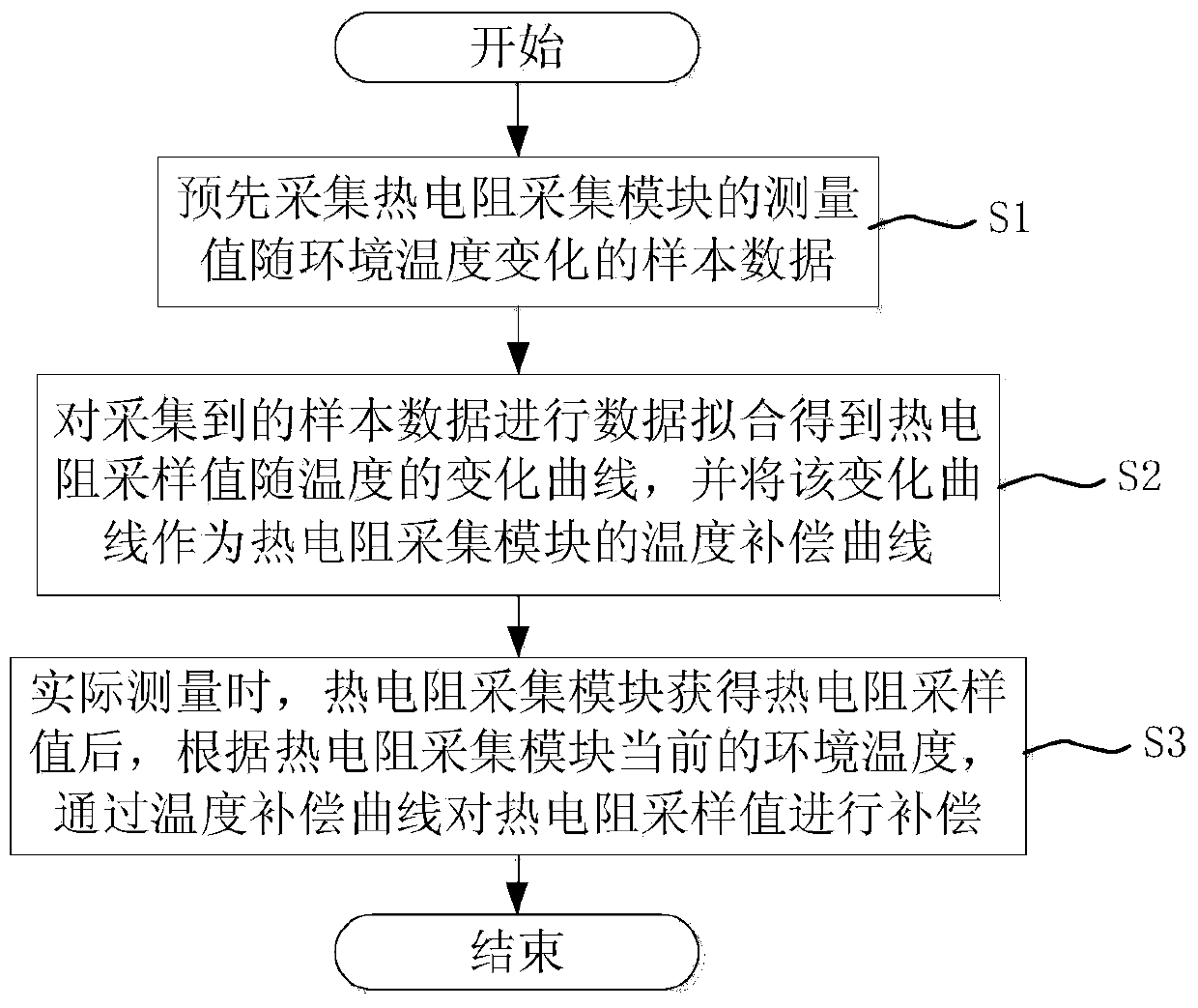
[0018] figure 1 It is a schematic diagram of the temperature compensation process for the thermal resistance acquisition module of the present invention.

[0019] See figure 1 , the temperature compensation method for thermal resistance acquisition module provided by the present invention comprises the following steps:

[0020] Step S1: Pre-collect sample data of changes in the measured value of the thermal resistance acquisition module with the ambient temperature. Considering the differences in the gain and sampling signal range of different types of thermal resistance input circuits, the temperature response curves of thermal resistance acquisition modules will be different. In order to minimize the measurement error of each type of thermal resistance, various types The thermal resistance was used for data acquisition and curve fitting respectivel...


PUM


Abstract

The invention discloses a temperature compensation method used for a thermal resistance collecting module. The method comprises the following steps that (a) sample data of measured values, changing along with the environment temperature, of the thermal resistance collecting module are collected in advance; (b) data fitting is conducted on the collected sample data to obtain a changing curve, along with the temperature, of thermal resistance sampled values, and the changing curve serves as a temperature compensating curve of the thermal resistance collecting module; (c) when actual measuring is conducted, after the thermal resistance collecting module obtains the thermal resistance sampled values, compensation is conducted on the thermal resistance sampled values through the temperature compensating curve according to the current environment temperature of the thermal resistance collecting module. According to the temperature compensation method used for the thermal resistance collecting module, the changing curve, along with the temperature, of the thermal resistance sampled values of the thermal resistance collecting module is obtained in advance, temperature compensation is conducted through the changing curve during actual measuring, and therefore the number of temperature measured deviations, caused by environment temperature changes, of the thermal resistance collecting module is reduced, measuring accuracy is greatly improved, and cost is not increased.

Description

technical field [0001] The invention relates to a thermal resistance sampling method, in particular to a temperature compensation method for a thermal resistance acquisition module. Background technique [0002] Thermal resistance is widely used in industrial field applications to measure temperature. Common thermal resistances include copper 50, copper 100, platinum 100, platinum 200, platinum 500, platinum 1000, etc. Compared with other temperature measurement sensors, thermal resistance sensors have the characteristics of high measurement accuracy and stable operation. When the temperature of the object to be measured changes, the resistance value of the thermal resistor changes accordingly, and the resistance value of the thermal resistor has a fixed correspondence with the measured temperature, so that the measured temperature value can be accurately obtained according to its resistance value. [0003] In the thermal resistance temperature measurement system, the therm...

Claims


Application Information

Patent Timeline
IPC IPC(8): G01K7/16
Inventor 薛志波林维生
Owner 万科思自控设备(中国)股份有限公司
Why Eureka
Try Eureka