Dynamic-compensation-based cleanliness factor detection method and device

A technology of dynamic compensation and cleaning factor, applied in the field of cleaning factor detection based on dynamic compensation, can solve the problems of shortening the life of the heating surface, reducing the reliability of the monitoring effect, and discounting the engineering applicability.

Active Publication Date: 2014-04-30
YANTAI LONGYUAN POWER TECH
View PDF4 Cites 6 Cited by
  • Summary
  • Abstract
  • Description
  • Claims
  • Application Information

AI Technical Summary

Problems solved by technology

This method has various problems such as blindness: on the one hand, overblowing will cause damage to the heating surface due to thermal stress and wear, shortening the life of the heating surface
From the perspective of application, if the pollution monitoring of the heating surface cannot be continuously and effectively monitored under such unsteady conditions, its engineering applicability will be greatly reduced
Although the pollution quantification calculation method under the existing technical conditions is relatively simple and effective, it will inevitably greatly reduce the applicable working conditions of the monitoring indicators, and at the same time reduce the credibility of the monitoring effect

Method used


Image

  • Dynamic-compensation-based cleanliness factor detection method and device
  • Dynamic-compensation-based cleanliness factor detection method and device
  • Dynamic-compensation-based cleanliness factor detection method and device

Examples


Embodiment Construction

[0066] The following will clearly and completely describe the technical solutions in the embodiments of the present invention with reference to the accompanying drawings in the embodiments of the present invention. Obviously, the described embodiments are only some, not all, embodiments of the present invention. The following description of at least one exemplary embodiment is merely illustrative in nature and in no way taken as limiting the invention, its application or uses. Based on the embodiments of the present invention, all other embodiments obtained by persons of ordinary skill in the art without creative efforts fall within the protection scope of the present invention.

[0067] The relative arrangements of components and steps, numerical expressions and numerical values ​​set forth in these embodiments do not limit the scope of the present invention unless specifically stated otherwise.

[0068] At the same time, it should be understood that, for the convenience of d...


PUM


Abstract

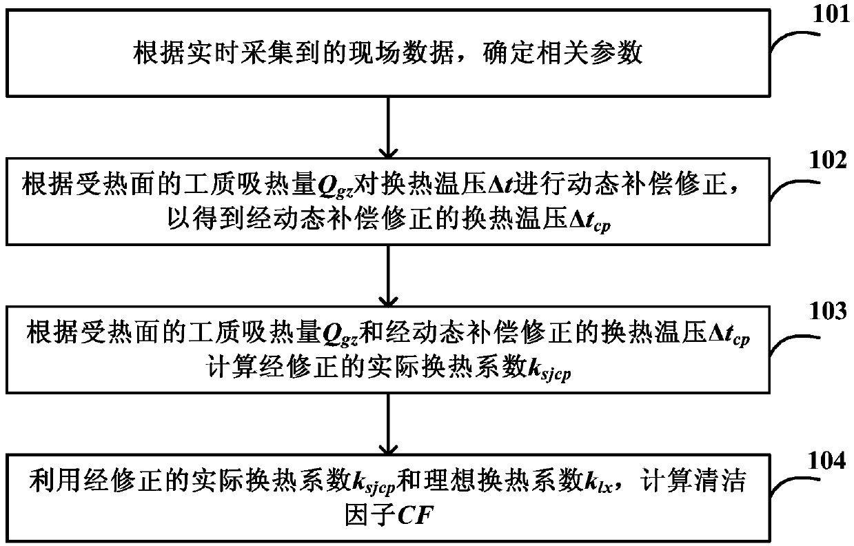
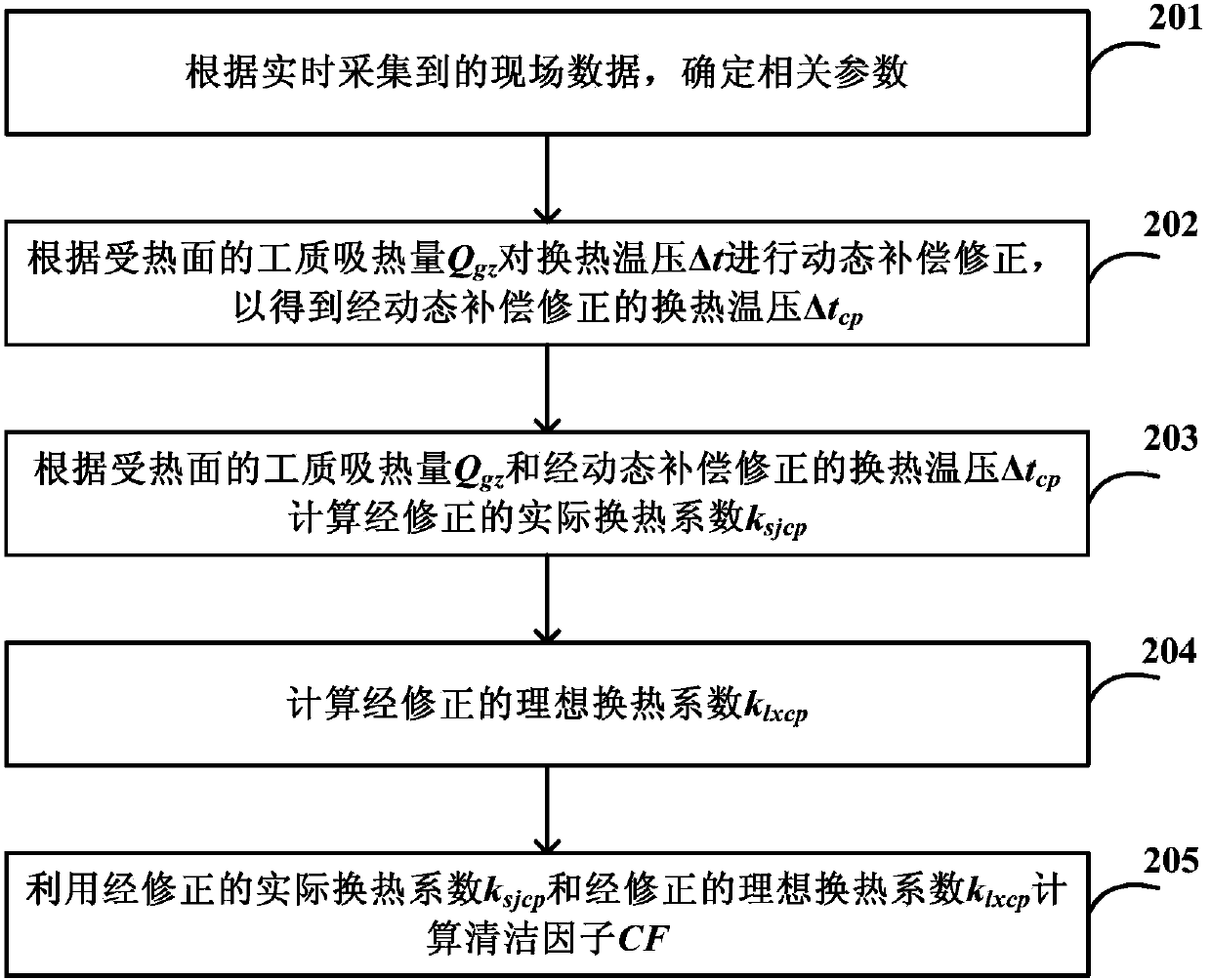
The invention discloses a dynamic-compensation-based cleanliness factor detection method and a dynamic-compensation-based cleanliness factor detection device. The dynamic-compensation-based cleanliness factor detection method comprises the following steps of determining the working medium heat absorption capacity Qgz, heat exchange temperature pressure Delta t and ideal heat exchange coefficient k1x of a heating surface according to field data acquired in real time, performing dynamic compensation and correction on the heat exchange temperature pressure Delta t according to the working medium heat absorption capacity Qgz of the heating surface to obtain a dynamically compensated and corrected actual heat exchange coefficient Deltatcp, calculating a corrected actual heat exchange coefficient ksjcp according to the working medium heat absorption capacity Qgz of the heating surface and the dynamically compensated and corrected heat exchange temperature pressure Delta tcp, and calculating a cleanliness factor CF by utilizing the corrected actual heat exchange coefficient ksjcp and the ideal heat exchange coefficient k1x. According to the method and the device, the heat exchange temperature pressure is dynamically compensated and corrected, so that dynamic response characteristics of a flue gas side and a working medium side tend to be consistent in a variable working condition process, the anomaly trend of a cleanliness factor calculation result under a variable working condition is effectively inhibited, the fluctuation of a calculated curve is relieved, and the calculation accuracy and the adaptability under all working conditions are enhanced.

Description

technical field [0001] The invention relates to the technical field of on-line monitoring of pollution on heating surfaces of large coal-fired boilers, in particular to a cleaning factor detection method and device based on dynamic compensation. Background technique [0002] At present, my country's power plants generally adopt the operation mode of blowing soot on the heating surface of the boiler along the flue gas flow at regular intervals. This method has various problems such as blindness: on the one hand, overblowing will cause the heating surface to be damaged due to thermal stress and wear, shortening the life of the heating surface. On the other hand, insufficient soot blowing will increase the exhaust gas temperature of the boiler, which will affect the economy of operation. Severe slagging on some heating surfaces will even cause boiler slagging accidents, which seriously threatens the safety of boiler operation. At present, the boiler intelligent soot blowing sy...

Claims


Application Information

Patent Timeline
Patent Type & Authority Applications(China)
IPC IPC(8): G01N25/20
Inventor 赵超石书雨隋海涛任旻王海鹏吕霞
Owner YANTAI LONGYUAN POWER TECH
Why Eureka
Try Eureka